Introduction to Photoelectric Sensing Fundamentals
Photoelectric sensors are ubiquitous in industrial automation, providing non-contact detection of objects based on the modulation of a light beam. Their reliability and versatility stem from a well-established internal architecture. Understanding the traditional structure diagram is crucial for engineers to select, install, and troubleshoot these devices effectively. The core principle involves three primary components: an emitter, a receiver, and a control circuit. The emitter generates a modulated light beam, which is either reflected off a target or interrupted by it. The receiver detects this light change and converts it into an electrical signal. Finally, the control circuit processes this signal to produce a clean, usable output for machinery control systems. This fundamental arrangement forms the basis for all photoelectric sensor variants.
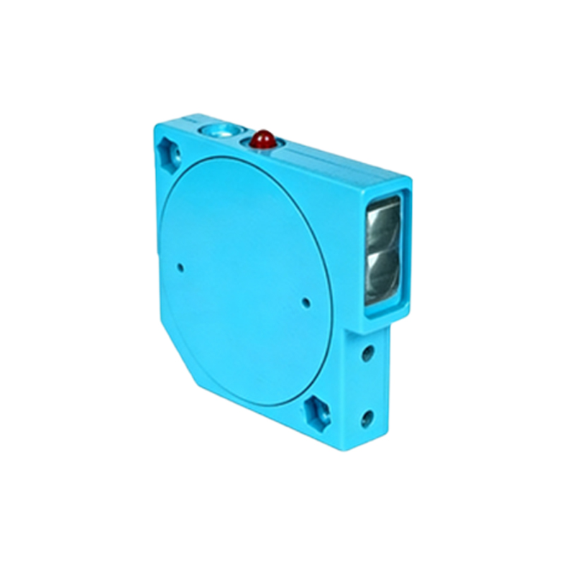
Detailed Breakdown of the Emitter Section
The emitter is the light source of the sensor. In traditional designs, this is typically a Light Emitting Diode (LED). For standard applications, a visible red LED is common, while for longer ranges or demanding environments, infrared LEDs are employed. The key component here is the emitter lens. This optical element collimates or focuses the emitted light into a precise beam. The quality of this lens directly impacts the sensor's sensing range and beam spot size. The LED is driven by an oscillator circuit within the control section, which modulates the light at a specific high frequency (often in the kHz range). This modulation is critical as it allows the receiver to distinguish the sensor's own light from ambient background light, significantly enhancing noise immunity and operational stability in brightly lit industrial settings.
Anatomy of the Receiver and Detection Circuitry
Opposite the emitter sits the receiver section. Its heart is a phototransistor or a photodiode, chosen for its sensitivity to the wavelength of light emitted by the paired LED. The receiver lens collects the incoming light and focuses it onto this light-sensitive element. When the emitted beam reaches the receiver (either directly or via reflection), the phototransistor conducts, generating a small electrical current. This minuscule signal is then fed into a high-gain amplifier. Following amplification, a demodulator circuit tuned to the emitter's modulation frequency filters out any DC component and uncorrelated AC signals (like ambient light flicker). This process ensures that only the intended modulated light signal triggers the sensor's output.
The Control and Output Switching Unit
The processed signal from the receiver is sent to a comparator circuit within the control unit. Here, it is compared against a preset threshold voltage. If the signal strength exceeds the threshold (indicating sufficient light on the receiver), the comparator's state changes. This state change drives the output switching device. Traditionally, this is an electromagnetic relay or a solid-state switch like a transistor or TRIAC. The output circuit is electrically isolated from the sensor's internal logic to protect it from voltage spikes and noise on the load side. This unit also houses components for setting operational modes (e.g., light-on or dark-on), sensitivity adjustment via a potentiometer, and often a stability indicator LED to show power and output status.
Common Housing and Optical Path Configurations
The structural diagram also encompasses the housing and the optical arrangement, which define the sensor type. In a through-beam sensor, the emitter and receiver are housed in two separate units, creating a direct, opposed optical path. The structure diagram shows two distinct enclosures. For a retro-reflective sensor, both emitter and receiver are in the same housing, facing a common lens. The diagram illustrates a single unit with a beam path to a reflector and back. A diffuse reflective sensor has a similar single-housing structure, but the optical path shows the beam projecting out and reflecting directly off the target object. The housing is designed to be rugged, typically from metal or robust plastic, with ingress protection (IP) ratings to withstand dust, moisture, and mechanical impact.
Interpreting Wiring and Connection Diagrams
Integral to the overall structure diagram is the terminal connection layout. Traditional sensors commonly have three or four wires. A standard three-wire DC sensor diagram will show connections for positive supply voltage (typically brown wire), common negative/ground (blue wire), and the switched output load wire (black wire). Four-wire models may include a second complementary output. The diagram clearly indicates the output type, such as NPN (sourcing) or PNP (sourcing), which is fundamental for correct integration with Programmable Logic Controller (PLC) input modules. It also shows protective components like reverse polarity protection diodes and surge suppression circuits for the output, which are essential for long-term reliability.
Application Considerations from Structural Design
Analyzing the traditional structure informs critical application decisions. The separation between emitter and receiver in through-beam models offers the longest sensing distance and highest reliability, as it is least affected by target color or surface finish. The single-body design of retro-reflective and diffuse sensors simplifies mounting but introduces considerations like the minimum sensing distance and sensitivity to object properties. The modulation frequency choice, evident from the oscillator in the diagram, determines immunity to specific ambient light sources. Furthermore, the presence of a sensitivity adjustment potentiometer in the control section allows engineers to fine-tune the sensor for challenging detection tasks, such as seeing transparent materials or ignoring background objects.