Understanding the Photoelectric Sensor Pink Wire
In industrial automation, photoelectric sensors are critical for object detection, positioning, and safety. The pink wire (often labeled as "pink" or "PK") is a common color code in 4-wire or 5-wire DC sensors, typically used for a specific output function. Unlike standard brown (power +), blue (power -), or black/white (outputs), the pink wire may serve as a secondary output, alarm signal, or test input, depending on the manufacturer. Always verify the datasheet before connection.
Standard Wiring Configuration for 4-Wire Sensors
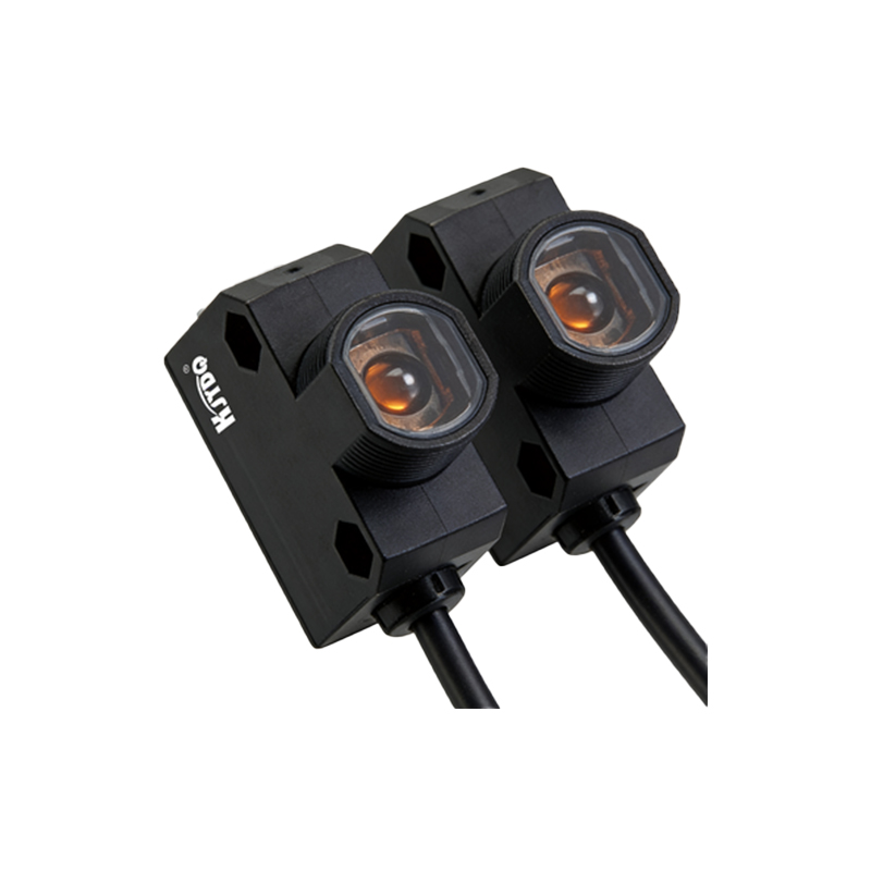
For most 4-wire photoelectric sensors (e.g., diffuse, retro-reflective, or through-beam types), the wiring is as follows:
- Brown wire: Connect to DC power supply positive (+), typically 10-30 VDC.
- Blue wire: Connect to DC power supply negative (-) or ground.
- Black wire: Main output (NPN or PNP, depending on model).
- Pink wire: Secondary output or auxiliary function.
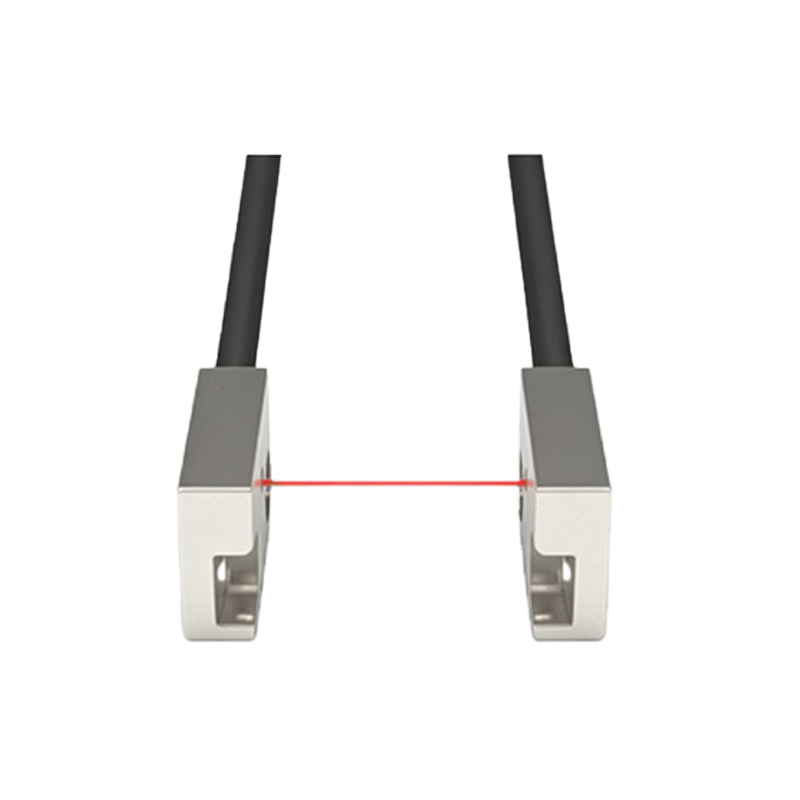
The pink wire often acts as an "alarm" or "stability" output. For example, in a Banner or SICK sensor, the pink wire may indicate a marginal sensing condition (e.g., low light margin). To use it, connect the pink wire to a PLC input or relay, ensuring the load is within the sensor's current rating (usually 100 mA).
Connecting the Pink Wire for NPN vs. PNP Sensors
The pink wire's behavior depends on the sensor's output type.
- For NPN sensors: The pink wire is typically an NPN open-collector output. Connect it to a pull-up resistor (e.g., 10 kΩ to +VDC) if the load requires a high signal, or directly to a sinking PLC input.
- For PNP sensors: The pink wire is a PNP output. Connect it directly to a sourcing PLC input or a load with a common ground.
Example: If using a PNP sensor with a pink wire for alarm, wire the pink to a PLC digital input (sourcing type). The input will go high when the alarm condition is active.
Using the Pink Wire as a Test Input
In some sensors (e.g., Omron E3Z series), the pink wire functions as a test input. Applying a voltage (e.g., +VDC for 100 ms) can trigger a self-test or disable the output. In this case:
- Do not leave the pink wire unconnected; tie it to ground (for active-low test) or to +VDC (for active-high test) per the manual.
- For normal operation, connect the pink wire to the appropriate state (e.g., ground for inactive).
Failure to terminate the test wire correctly may cause erratic sensor behavior.
Troubleshooting Common Pink Wire Issues
If the sensor is not functioning as expected:
1. Verify the pink wire voltage: Use a multimeter to check between pink and blue. It should match the datasheet (e.g., 0V or +VDC in idle state).
2. Check for short circuits: A damaged pink wire can cause false alarms or output lockout.
3. Confirm load compatibility: The pink wire output may be rated for lower current (e.g., 50 mA) than the main black wire (100 mA).
4. Review the wiring diagram: Some sensors require a 5-wire configuration where pink and white are paired for complementary outputs.
Safety and Best Practices for Industrial Wiring
Always power off the system before connecting wires. Use shielded cable for long runs (over 10 meters) to reduce electromagnetic interference. Label the pink wire clearly in the junction box to avoid confusion with other auxiliary wires. For high-vibration environments, apply strain relief and secure connections with screw terminals or M12 connectors. Finally, test the sensor with a known load before integrating into the control system.