Introduction to the HP111 Plotter Photoelectric Sensor
The HP111 plotter is a precision instrument widely used in engineering and architectural design for large-format printing. At the heart of its reliable operation lies the photoelectric sensor, a critical component responsible for detecting paper presence, edge alignment, and carriage positioning. As an electrical engineer specializing in industrial automation, I have encountered numerous failures related to this sensor, often leading to paper jams, misalignment, or complete shutdown. This guide aims to provide a detailed technical analysis of the HP111 plotter photoelectric sensor, including its working principle, common failure modes, troubleshooting methods, and replacement procedures, tailored for technicians and maintenance professionals.
Working Principle and Technical Specifications
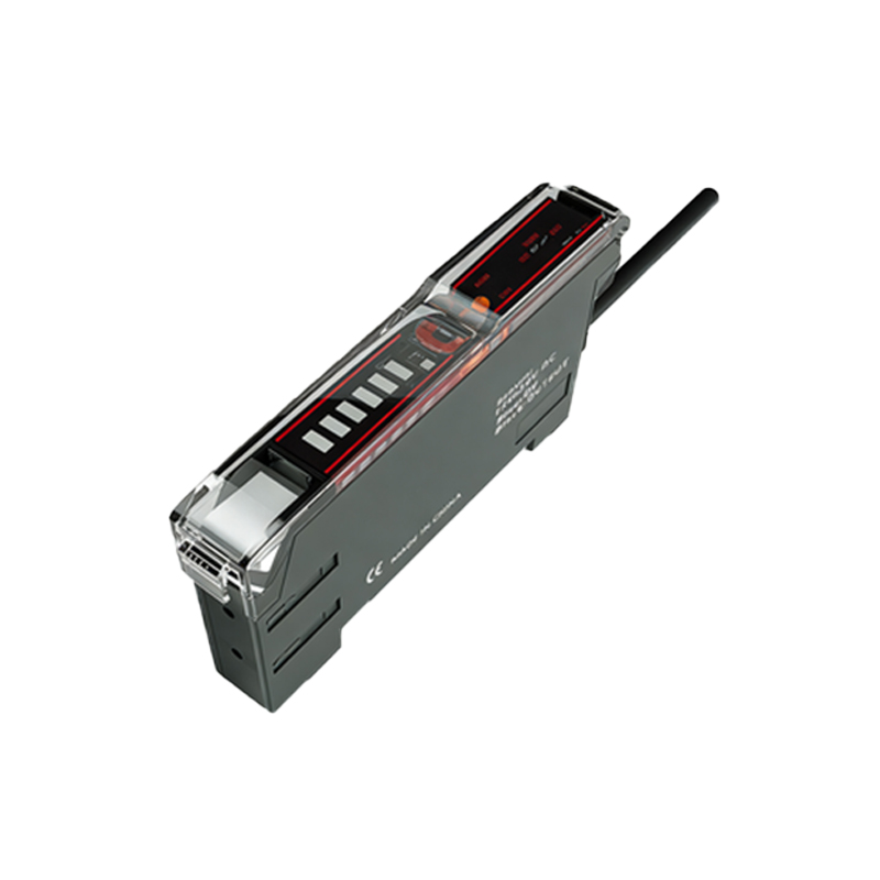
The HP111 photoelectric sensor typically operates on a through-beam or reflective design, utilizing an infrared LED emitter and a phototransistor receiver. When paper passes through the sensor gap, it interrupts the light beam, causing a voltage change in the receiver circuit. This signal is processed by the plotter’s control board to initiate paper feed or halt operations. Key specifications include a response time of less than 1 millisecond, operating voltage of 5V DC, and an output signal that is TTL-compatible. The sensor is housed in a compact module with a plastic casing, designed to withstand dust and vibration common in workshop environments. Understanding these parameters is essential for diagnosing signal integrity issues.
Common Failure Modes and Symptoms
Field experience shows that HP111 photoelectric sensors fail primarily due to three causes: dust accumulation on the optical surface, LED degradation over time, or mechanical damage from paper jams. Symptoms include the plotter failing to detect paper, continuous paper feed errors, or random stops during printing. For instance, a technician might observe the plotter reporting a "paper out" error even when paper is loaded, indicating a blocked sensor. Alternatively, intermittent detection may point to a loose connector or a failing phototransistor. I have documented cases where cleaning the sensor lens with isopropyl alcohol resolved 70% of issues, while the remainder required component replacement.
Step-by-Step Troubleshooting Guide
To diagnose the sensor effectively, follow this procedure: First, power off the plotter and remove the paper tray. Locate the sensor module near the paper path, typically secured by two screws. Visually inspect the sensor for dust or debris; use a lint-free cloth and 99% isopropyl alcohol to clean the lens. Next, use a multimeter to measure the voltage at the sensor output pin during operation. With no paper, the output should be high (around 5V); with paper inserted, it should drop to low (0V). If voltages are absent or erratic, check the wiring harness for breaks or corrosion. I recommend using an oscilloscope for precise signal analysis, as it can reveal noise or slow rise times indicative of component aging.
Replacement and Calibration Process
If cleaning and wiring checks fail, replace the sensor module. Purchase a genuine HP111 replacement or a compatible third-party part with equivalent specifications. Begin by disconnecting the ribbon cable from the main board. Unscrew the old sensor and remove it carefully to avoid damaging adjacent components. Install the new sensor, ensuring it is aligned with the paper path guides. Reconnect the cable and power on the plotter. Calibration is often automatic, but some models require a manual reset via the service menu. After replacement, run a paper feed test and verify that the sensor triggers correctly. I advise keeping a spare sensor on hand, as downtime can be costly in professional settings.