Introduction to Photoelectric Sensors
Photoelectric sensors are widely used in industrial automation for detecting the presence, absence, or distance of objects. Operating on 220V AC, these sensors offer reliable performance in harsh environments. Understanding their wiring is crucial for ensuring safety and functionality. This guide provides a comprehensive overview of wiring practices, tailored for engineers and technicians in the electrical field. Proper installation not only enhances sensor longevity but also prevents operational failures in automated systems.
Components and Specifications
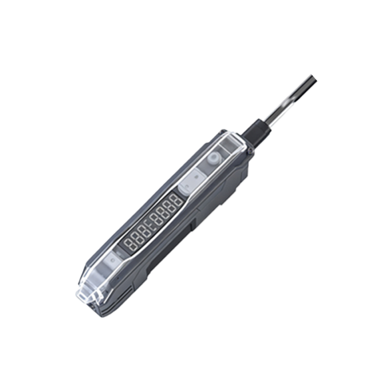
A typical 220V photoelectric sensor consists of a light emitter, receiver, and output circuit. Key specifications include sensing range, response time, and output type (e.g., NPN or PNP for DC models, but AC versions often use relay or solid-state outputs). For 220V AC sensors, the input voltage range is usually 100-240V AC, with outputs capable of switching high loads. Always refer to the manufacturer's datasheet for exact ratings, as incorrect wiring can lead to damage or hazards. Components may include power terminals, output terminals, and adjustment knobs for sensitivity.
Wiring Diagram and Connections
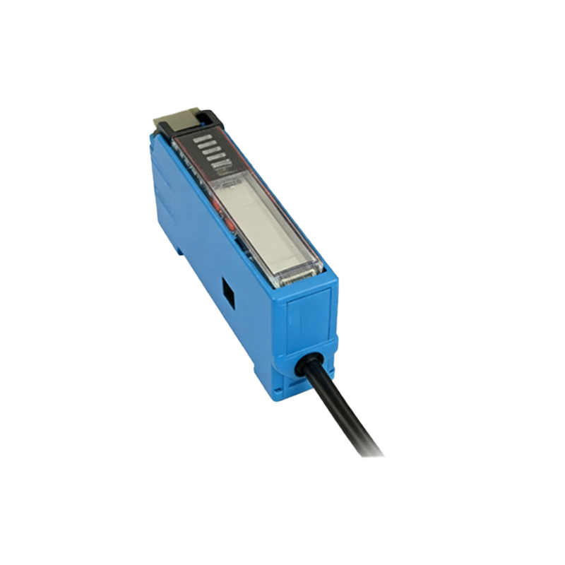
The wiring process involves connecting the sensor to a 220V AC power supply and the load. Typically, three wires are used: brown (live or line), blue (neutral), and black (output). Connect the brown wire to the 220V AC line, the blue wire to the neutral, and the black wire to the load (e.g., a relay or PLC input). Ensure the load is compatible with the sensor's output current rating. A protective earth wire (green/yellow) may be included for grounding. Follow the diagram provided in the sensor manual, and double-check connections to avoid short circuits.
Safety Precautions
When wiring 220V photoelectric sensors, safety is paramount. Always disconnect power before starting work. Use insulated tools and wear protective gear to prevent electric shock. Verify that the voltage matches the sensor's rating—applying incorrect voltage can cause overheating or failure. Install fuses or circuit breakers in the power line to protect against overcurrent. Regularly inspect wiring for wear or damage, especially in high-vibration areas. Adhering to local electrical codes and standards, such as IEC or NEC, ensures compliance and reduces risks.
Testing and Troubleshooting
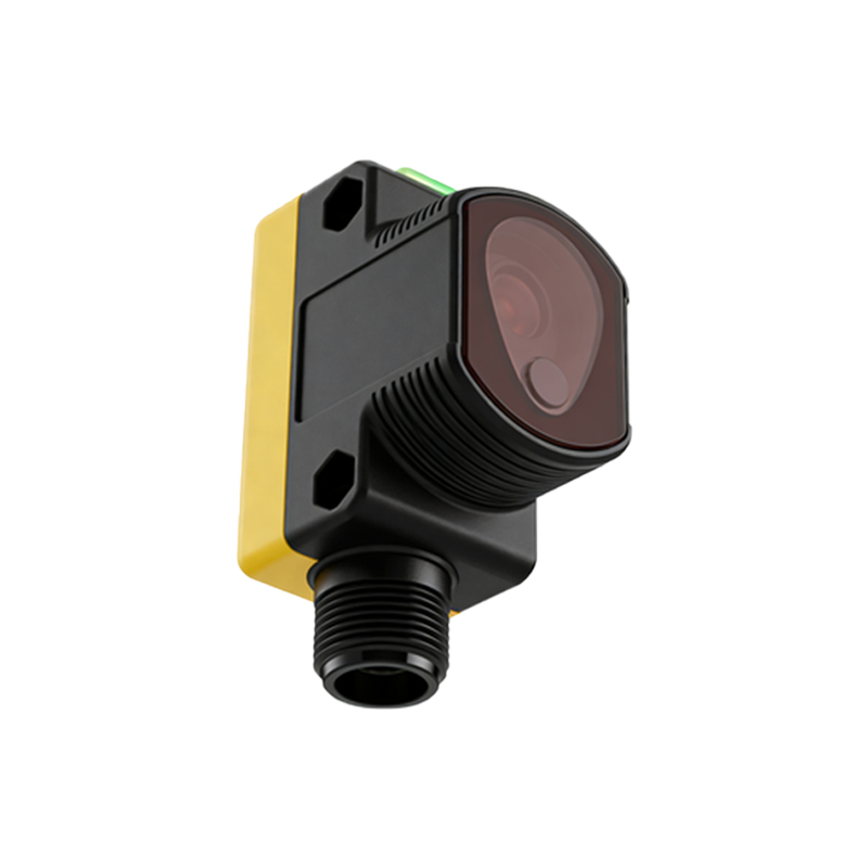
After wiring, test the sensor by applying power and observing its indicator lights. Most sensors have LED indicators for power and output status. If the sensor fails to detect objects, check the alignment of the emitter and receiver, and adjust sensitivity if available. Use a multimeter to measure voltage at the terminals, ensuring it's within 220V ±10%. Common issues include loose connections, incorrect polarity (for DC models), or environmental interference like dust or bright light. Consult the troubleshooting section of the manual for specific guidance.
Applications and Best Practices
220V photoelectric sensors are ideal for industrial settings such as conveyor systems, packaging machines, and safety barriers. For optimal performance, mount sensors securely to minimize movement, and keep lenses clean to maintain accuracy. Consider using shielded cables in areas with electromagnetic interference. Implement regular maintenance schedules to check for degradation. By following best practices, you can enhance system reliability and reduce downtime, contributing to efficient automation processes.