Understanding the Ring Photoelectric Sensor
A ring photoelectric sensor, often referred to as a ring sensor or fork sensor, is a specialized type of through-beam sensor. It consists of a U-shaped or ring-like housing that contains both an emitter and a receiver facing each other across a gap. The object to be detected passes through this aperture, interrupting the light beam. This non-contact detection method is ideal for high-speed counting, small part detection, and verifying the presence of components like screws, nuts, or wires on assembly lines. Unlike diffuse or retro-reflective sensors, the through-beam design of a ring sensor provides a highly reliable and precise sensing field, largely immune to the color, reflectivity, or surface finish of the target object.
Pre-Installation Considerations and Selection
Before beginning the adjustment process, correct sensor selection is paramount. Key specifications include the aperture size, which must be larger than the object to be detected, and the beam type. Some ring sensors offer a single, concentrated beam for pinpoint accuracy, while others provide a curtain of multiple beams to detect objects that may not pass perfectly through the center. The response time must be faster than the interval between passing objects. Additionally, consider the environmental factors: select sensors with appropriate IP ratings for dust and moisture protection and ensure the housing material (often stainless steel or rugged plastic) is suitable for the application environment, including potential exposure to coolants or washdowns.
Mechanical Alignment and Mounting
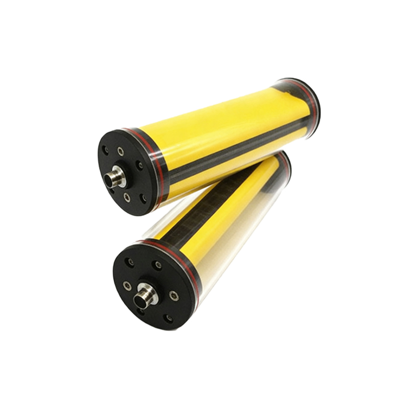
Secure and precise mounting is the foundation for reliable operation. The sensor must be rigidly fixed to the machine frame or bracket to prevent vibration-induced misalignment. The most critical aspect is ensuring the path of the objects is perfectly centered through the aperture. Misalignment can cause objects to graze the sensor housing or only partially interrupt the beam, leading to inconsistent detection. Use alignment tools or fixtures if provided. For conveyor applications, guides or rails before and after the sensor can help funnel objects through the center. Always allow sufficient clearance around the sensor for easy access during initial setup and future maintenance.
Electrical Wiring and Power Connection
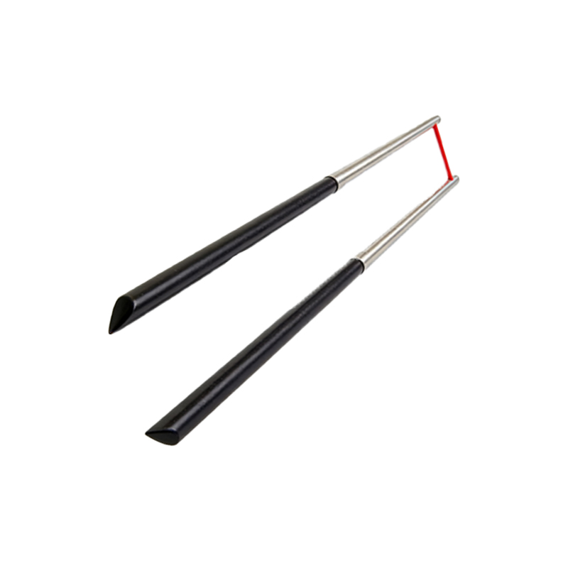
Follow the manufacturer's wiring diagram precisely. Most industrial ring sensors operate on 10-30V DC and provide either a digital PNP (sourcing) or NPN (sinking) output signal. Ensure the power supply voltage is stable and within the sensor's specified range to prevent erratic behavior. Use shielded cables in electrically noisy environments, grounding the shield at the controller end only. Connect the output wire to the correct input module on your PLC or counter. It is good practice to implement a slight delay in the PLC logic to debounce the signal, filtering out any electrical noise that might cause false counts.
Initial Sensitivity and Threshold Adjustment
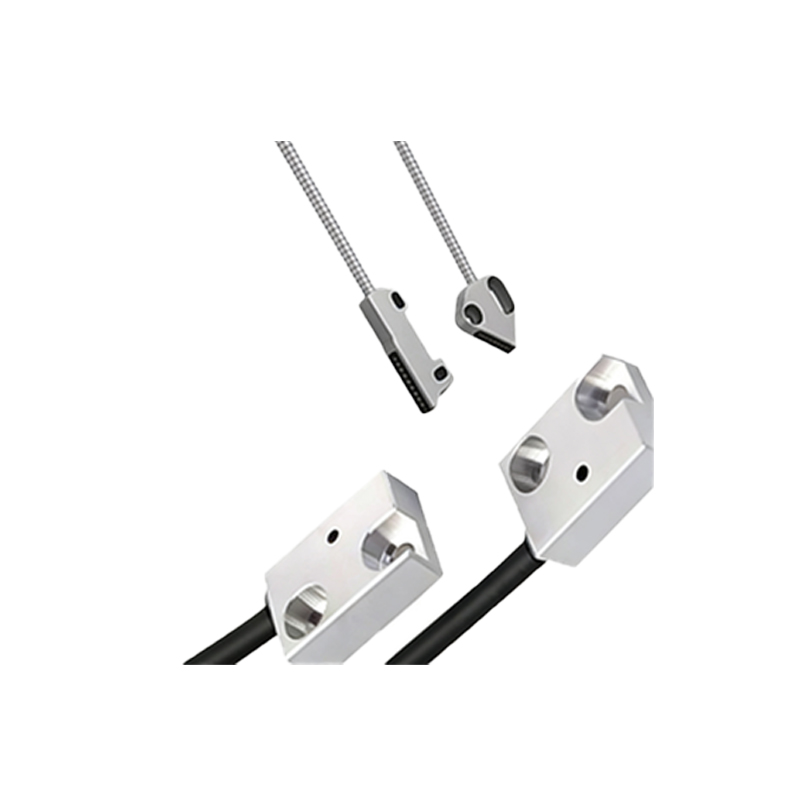
Modern ring photoelectric sensors feature a sensitivity adjustment potentiometer or a teach-in button. The sensitivity setting defines the threshold at which the beam interruption is recognized as a valid detection. After powering the sensor, perform an initial adjustment without any objects present. For potentiometer-based models, turn the screw until the output indicator (often an LED) is in a stable "beam received" state. For models with a teach function, press the button when the aperture is clear. This sets the baseline light intensity. The goal is to set the sensitivity high enough to reliably detect the smallest target but low enough to ignore ambient light changes, dust, or vibration.
Dynamic Testing and Fine-Tuning with Targets
This is the most crucial step. Run your actual target objects through the sensor at the normal operational speed. Observe the sensor's output indicator and monitor the signal on your PLC or counter. If detections are missed, gradually increase the sensitivity. If the sensor gives false triggers (e.g., from flying debris, splashing liquid, or rapid ambient light changes), decrease the sensitivity. For sensors with a response time adjustment, you may fine-tune it to match the object's speed, ensuring a clean, brief output pulse. Test with a representative sample of objects, including those at the extremes of your tolerance (e.g., smallest size, darkest color).
Troubleshooting Common Detection Issues
Missed detections often stem from insufficient sensitivity, misalignment, objects passing outside the beam area, or a response time that is too slow. False triggers are commonly caused by excessive sensitivity, external light interference (sunlight, strobe lights), reflective surfaces near the aperture, or electrical noise. For light interference, many sensors offer a modulated infrared light source; ensure this feature is enabled. Physical barriers or shrouds can be added to block ambient light. If instability persists, verify power supply quality, check for loose connections, and inspect the lens for contamination from oil or dust, cleaning it with a soft cloth if necessary.
Advanced Features and Integration Tips
Utilize advanced features for complex applications. Models with dual digital outputs can provide separate signals for "beam made" and "beam broken" states. Analog output versions can measure the degree of beam interruption, useful for detecting partial fills or diameter checks. For high-speed counting, ensure your sensor's maximum switching frequency exceeds the required rate. When integrating with a PLC, consider using a high-speed counter input module. Implement logical routines to monitor for jams (unexpectedly long beam blockage) or feed failures (absence of expected breaks) to enhance system diagnostics and prevent downstream process issues.
Routine Maintenance and Calibration Checks
Establish a preventive maintenance schedule. Periodically inspect the sensor for physical damage and clean the emitter and receiver lenses to maintain optimal light transmission. Re-check the alignment, as machine vibration can loosen mounts over time. Verify the detection stability by running test samples. In critical applications, a weekly or monthly calibration check is advisable. Document the optimal sensitivity setting (e.g., number of turns from minimum) so it can be quickly restored after a power cycle or sensor replacement. Keeping a log of performance and any adjustments aids in long-term reliability and quick troubleshooting.