Introduction to Three-Wire Photoelectric Sensors
A three-wire photoelectric sensor is a fundamental component in industrial automation, widely used for object detection, counting, and positioning. Unlike two-wire sensors that are directly connected in series with the load, three-wire sensors feature separate power, ground, and output signal wires. This design offers superior performance, including faster response times, higher switching accuracy, and better immunity to electrical noise. The standard wire color coding for DC models typically includes brown for positive voltage, blue for ground or negative, and a third color—often black—for the output signal. Understanding the role of each wire, particularly the black wire, is crucial for correct installation, reliable operation, and effective troubleshooting in any control system.
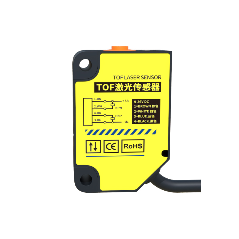
The Specific Role of the Black Wire
In the vast majority of DC-powered three-wire photoelectric sensors, the black wire serves as the switched output line. Its function is to carry the load current from the sensor's internal switching element (typically a transistor) to the controlled device, such as a programmable logic controller (PLC) input, relay, or indicator lamp. The sensor acts as a switch on this black wire. When the sensor detects the target object (in a diffuse, retro-reflective, or through-beam mode), it changes the state of this internal switch. For a sinking (NPN) output sensor, the black wire connects the load to ground (0V), completing the circuit when active. For a sourcing (PNP) output sensor, the black wire supplies positive voltage (+V) to the load when active. Misidentifying this wire can lead to incorrect wiring, which may prevent the system from functioning or, worse, cause damage to the sensor or the controller.
Standard Wiring Configurations and Practices
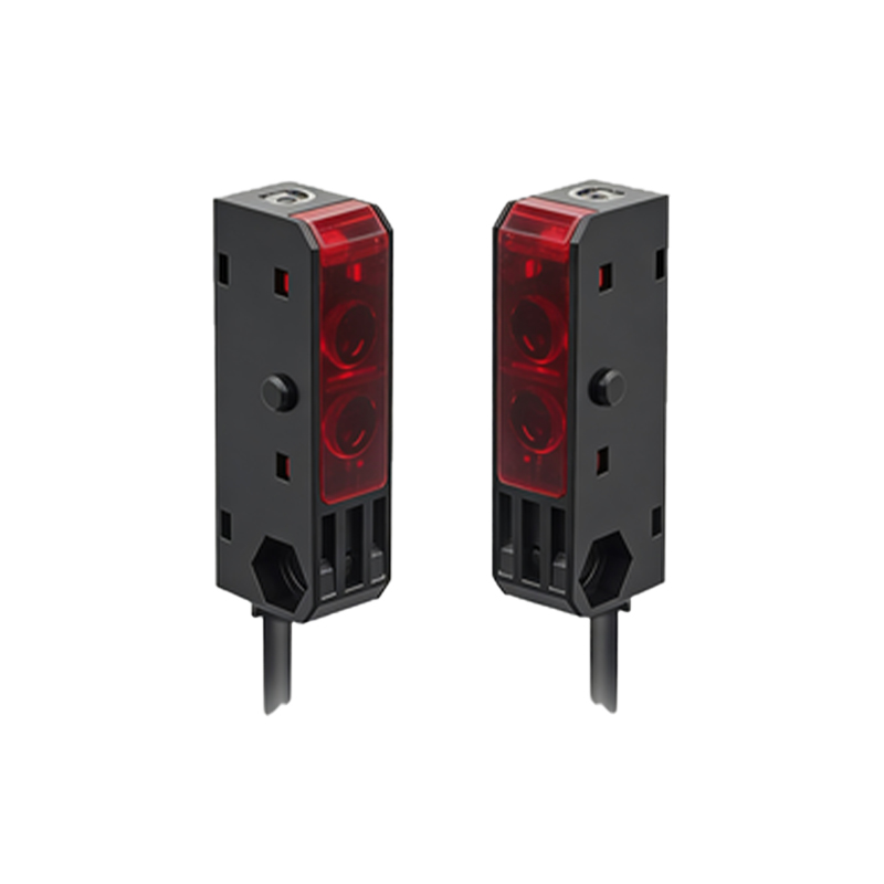
Correct wiring is paramount for safety and functionality. Always consult the sensor's datasheet first, as color codes can vary by manufacturer. For a common 24V DC sensor: Connect the brown wire to the positive DC supply voltage (+24V). Connect the blue wire to the DC common or ground (0V). The black output wire is then connected to the load. The other side of the load must be connected to the opposite supply rail to complete the circuit. For an NPN (sinking) sensor, the load is connected between the positive supply and the black wire. When activated, the black wire "sinks" current to ground. For a PNP (sourcing) sensor, the load is connected between the black wire and ground. When activated, the black wire "sources" current from the positive supply. Proper use of fuses or circuit breakers, secure connections, and protection against voltage spikes and short circuits are essential industry practices.
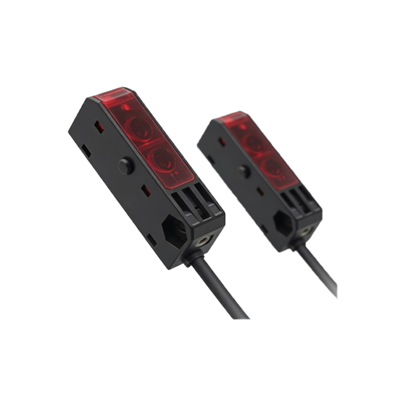
Common Issues and Troubleshooting the Black Wire Circuit
Problems often manifest as a sensor that fails to trigger an output. A systematic approach to troubleshooting the black wire circuit is recommended. First, verify power and ground at the sensor (brown and blue wires) using a multimeter. If power is correct, check the sensor's operation by observing its indicator LED. If the indicator suggests correct detection but the output fails, focus on the black wire circuit. Disconnect the black wire from the load. Use the multimeter to measure voltage between the black wire and the blue wire (for a PNP sensor) or between the brown wire and the black wire (for an NPN sensor) while triggering the sensor. A change in voltage indicates a functioning sensor output. If the sensor output is good, the issue lies in the load wiring, the load itself, or the PLC input module. Ensure the load's voltage and current ratings are compatible with the sensor's output specifications.
Selecting Between NPN and PNP Output Types
The choice between an NPN (sinking) and PNP (sourcing) sensor, which defines the black wire's behavior, is often dictated by the control system's input card design. In many regions, PNP sensors are more common for PLCs because they source positive voltage to the input card, which is often designed to accept a "high" signal as active. NPN sensors are also widely used, especially in systems where it is preferable to switch the ground side of the load. It is critical to maintain consistency within a system. Mixing NPN and PNP sensors on the same PLC input module without proper isolation can cause malfunctions. Understanding this distinction ensures the black wire is integrated correctly into the overall control logic, preventing wiring errors and ensuring reliable signal transmission for machine automation sequences.
Maintenance and Best Practices for Longevity
To ensure the long-term reliability of the sensor and its output circuit, regular maintenance is advised. Periodically inspect the wiring, especially at connection points, for signs of corrosion, looseness, or physical damage. Keep the sensor's lens clean from dust, oil, or debris that could affect its optical performance and cause erratic output switching. In electrically noisy environments, consider using shielded cable for the sensor wires, with the shield properly grounded at one end only, to protect the signal integrity on the black wire. Always power down the circuit before making any wiring changes. Adhering to these best practices minimizes downtime, prevents false triggers or missed detections, and extends the operational life of the three-wire photoelectric sensor in demanding industrial applications.