Introduction to Photoelectric Sensor Grounding
Proper grounding is a critical aspect of ensuring the reliable and safe operation of photoelectric sensors in industrial automation systems. These sensors, which detect the presence, absence, or distance of objects using a light transmitter and receiver, are susceptible to electrical noise, interference, and potential damage without correct grounding practices. A clear and standardized grounding identification diagram serves as an essential reference for engineers and technicians during installation, maintenance, and troubleshooting. This guide delves into the components, symbols, and best practices depicted in a typical photoelectric sensor grounding identification diagram, aligning with international electrical standards.
Key Components in the Grounding Diagram
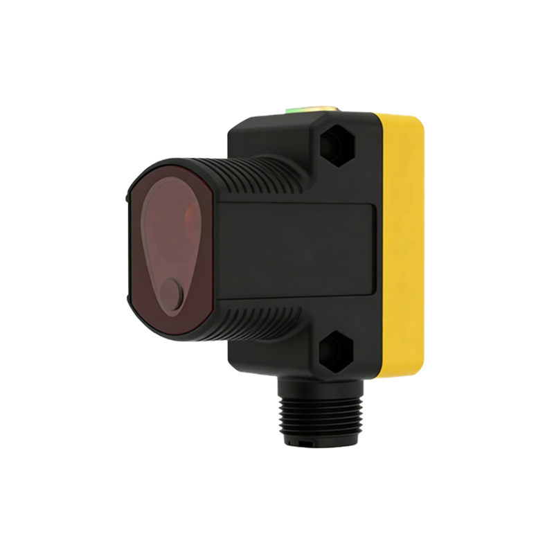
A standard photoelectric sensor grounding identification diagram illustrates several key components. The sensor itself is represented, showing the connection points for the power supply, output signal, and crucially, the ground terminal. The diagram explicitly labels the earth ground symbol, often depicted as a series of horizontal lines decreasing in length. It shows the grounding conductor path from the sensor's ground terminal to the central grounding point or busbar within the control panel. Furthermore, it may include representations of the metal sensor housing or mounting bracket, indicating if these should be bonded to ground for shielding purposes. The power supply common (0V) is typically shown separately to clarify the distinction between safety ground and signal reference.
Understanding Grounding Symbols and Labels
Interpreting the symbols on the diagram is fundamental. The international symbol for protective earth ground (IEC 60417-5017) is universally used. Labels such as "PE", "GND", or the ground symbol itself are placed adjacent to the appropriate terminal on the sensor's connection diagram. The diagram uses distinct line styles: a solid line for the protective earth conductor and dashed lines for signal paths. Arrows or notes often specify the required wire gauge for the ground connection, which must be equal to or larger than the power conductors. Color coding is also indicated, with green, green-yellow stripes, or bare copper being the standard for grounding wires in most regions.

Wiring Practices and Connection Sequence
The diagram enforces correct wiring practices. It emphasizes that the grounding conductor should be the first connected and the last disconnected, ensuring the sensor is always grounded when powered. It shows a dedicated, low-impedance path to ground, avoiding daisy-chaining ground connections from multiple devices, which can create ground loops. For sensors in remote or hazardous locations, the diagram might illustrate the connection to a local ground rod, which is then bonded to the main facility ground. Proper termination techniques, such as using ring terminals and ensuring metal-to-metal contact on clean, unpainted surfaces, are often highlighted in accompanying notes.
Noise Immunity and Shielding Grounding
A significant section of the diagram addresses noise immunity. For sensors using analog outputs (4-20mA, 0-10V) or high-frequency switching, the diagram details the grounding of cable shields. It typically shows the shield of the signal cable being connected to the ground terminal at the sensor end only, creating a drain path for electromagnetic interference (EMI) without forming a loop. In cases of severe noise, the diagram may prescribe a separate grounding scheme for the sensor body to act as a Faraday cage, diverting noise away from the sensitive internal electronics.
Compliance with Electrical Standards
The grounding identification diagram is not a suggestion but a compliance document. It is designed to meet the requirements of standards such as IEC 60204-1 (Safety of Machinery), NFPA 79 (Electrical Standard for Industrial Machinery), and UL 508A. These standards mandate specific grounding methods for operator safety and equipment protection. The diagram ensures that the installation meets the criteria for ground fault current paths, which are vital for triggering overcurrent protection devices in the event of an insulation failure.
Troubleshooting Based on the Grounding Diagram
When a photoelectric sensor malfunctions—exhibiting erratic behavior, false triggers, or communication errors—the grounding diagram is the first tool for diagnosis. Technicians use it to verify the physical integrity and continuity of the ground path, measure resistance between the sensor ground terminal and the main ground point (should be less than 1 ohm), and check for improper shield connections. The diagram helps isolate whether an issue is due to a faulty ground, which is a common root cause of intermittent problems in sensitive electronic sensors.
Conclusion and Best Practices Summary
In summary, a photoelectric sensor grounding identification diagram is a vital blueprint for system integrity. Always refer to the manufacturer-specific diagram provided in the sensor's datasheet or manual, as terminal locations can vary. The core best practices it communicates are: use a dedicated, robust ground wire; connect shields correctly to prevent noise; ensure all metal parts are bonded; and verify the grounding system complies with local and international safety codes. Adherence to this diagram minimizes downtime, prevents damage, and guarantees the sensor performs accurately within the automated system's electrical environment.