Introduction to Photoelectric Sensor Wiring
Photoelectric sensors are widely used in industrial automation for detecting objects, counting, and positioning. Proper wiring is crucial for their reliable operation. Among the various wires, the black wire often plays a key role, typically serving as the output or signal line. Understanding where to connect the black wire ensures the sensor functions correctly within a control system. This guide provides a detailed overview based on common industry standards and practices.
Understanding Wire Color Codes
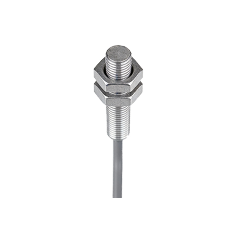
In photoelectric sensors, wire colors follow standard conventions to simplify installation. The black wire is commonly designated as the output wire, carrying the signal from the sensor to a controller like a PLC. Other wires include brown for positive power supply, blue for negative or ground, and sometimes white for complementary output. However, it's essential to consult the specific sensor's datasheet, as colors can vary by manufacturer. Miswiring can lead to malfunctions or damage, so always verify the wiring diagram provided with the device.
Connecting the Black Wire to a PLC
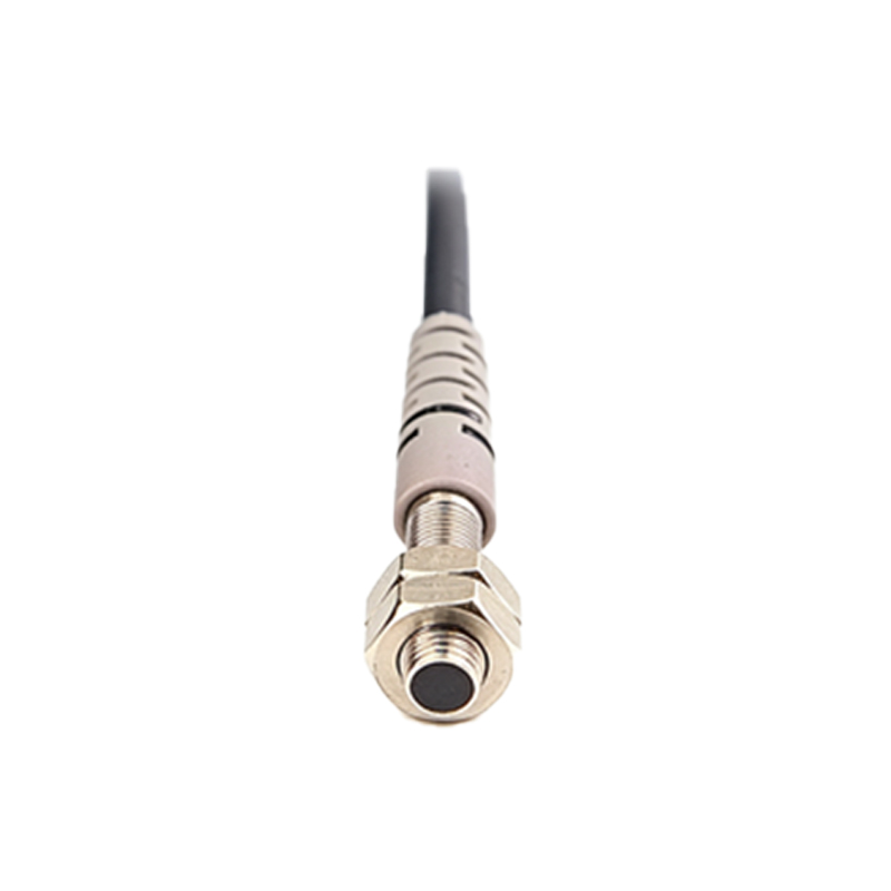
When integrating a photoelectric sensor with a Programmable Logic Controller (PLC), the black wire usually connects to an input terminal. For a sinking sensor output, the black wire links to the PLC's input point, while the power supply completes the circuit. In sourcing configurations, the connection may differ. Ensure the PLC and sensor voltage ratings match—commonly 12-24V DC. Use shielded cables for the black wire in noisy environments to prevent interference, and secure connections tightly to avoid loose contacts that could disrupt signals.
Black Wire in NPN vs. PNP Configurations
The function of the black wire depends on whether the sensor uses NPN or PNP transistor outputs. In NPN sensors, the black wire is the output that switches the negative side; it connects to the load, which then links to positive voltage. For PNP sensors, the black wire switches the positive side, connecting directly to the load and then to ground. Confusing these can cause the sensor to fail. Always check the sensor label or manual to identify the type, and wire accordingly to ensure compatibility with your system's logic.
Practical Installation Steps
Start by disconnecting power to prevent electrical hazards. Identify the black wire from the sensor cable—it's often labeled or grouped with other wires. Refer to the sensor's documentation for the exact pinout. If connecting to a relay or timer, attach the black wire to the input terminal, ensuring proper insulation. Test the connection with a multimeter to verify signal continuity. Once secured, power the system and observe the sensor's indicator LED to confirm operation. Regular maintenance checks can prevent issues like corrosion or wear over time.
Troubleshooting Common Issues
If the photoelectric sensor isn't working, the black wire connection is a common culprit. Check for loose or incorrect wiring—ensure the black wire is connected to the right terminal and isn't shorted with other wires. Use a voltmeter to measure the output voltage on the black wire; it should change when an object is detected. If there's no signal, inspect for damaged cables or faulty sensors. Environmental factors like dust or moisture can also affect performance, so consider protective enclosures for long-term reliability.
Safety and Best Practices
Always follow safety guidelines when wiring photoelectric sensors. Turn off power before making connections to avoid shocks or equipment damage. Use appropriate tools, such as wire strippers and screwdrivers, and ensure cables are routed away from moving parts or heat sources. Label wires, including the black wire, for easy identification during maintenance. Adhere to local electrical codes and standards, and train personnel on proper handling. Regular inspections can extend sensor life and enhance system efficiency.
Conclusion and Summary
Connecting the black wire of a photoelectric sensor correctly is vital for optimal performance in automation systems. Typically, it serves as the output line, interfacing with PLCs, relays, or controllers based on NPN or PNP configurations. Always reference the manufacturer's wiring diagram to avoid errors. By following standard practices and troubleshooting steps, you can ensure reliable detection and operation. For complex setups, consult with an expert or supplier to tailor the installation to your specific needs.