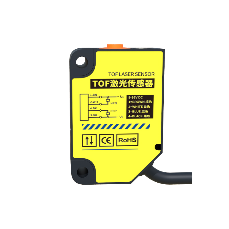
Introduction to Photoelectric Sensor Operation
Photoelectric sensors are fundamental components in industrial automation, relying on light beams to detect the presence, absence, or distance of objects. The core principle involves an emitter projecting a light beam—often infrared, visible red, or laser—towards a receiver. When an object interrupts this beam, the sensor's output state changes, triggering a control action. The expectation is clear: an obstruction should cause a detectable event, typically indicated by an LED on the sensor housing. However, a common and perplexing field issue is when an object blocks the beam, yet the sensor's indicator fails to illuminate, and no output signal is generated. This failure negates the sensor's primary function and can lead to production stoppages or safety concerns. Understanding the root causes requires a systematic examination of the sensor system beyond the simple act of blocking the light path.
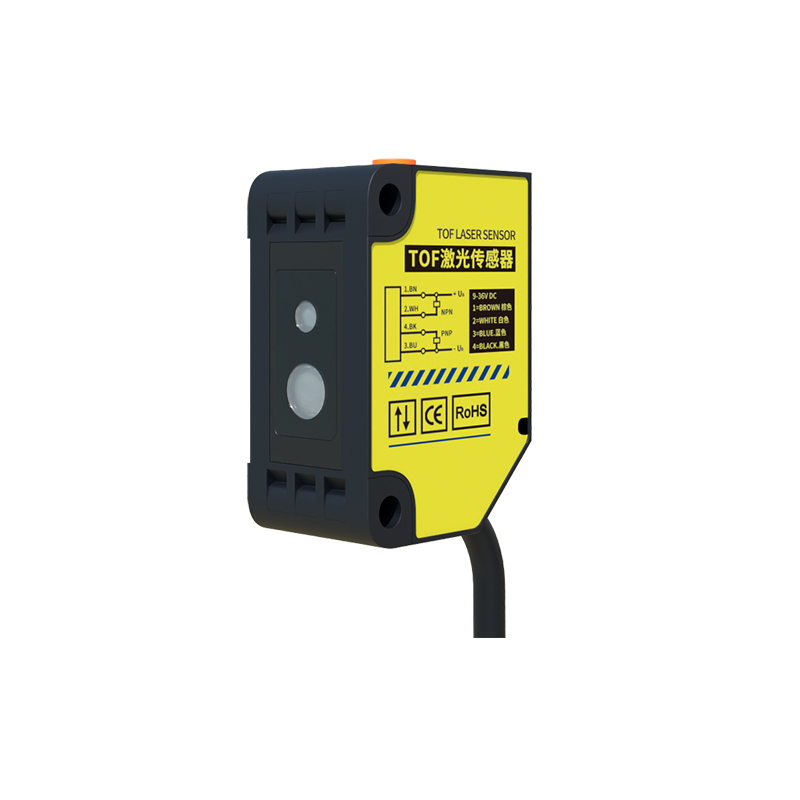
Primary Cause: Power Supply and Wiring Faults
The most elementary, yet frequently overlooked, cause is an issue with electrical supply. A photoelectric sensor cannot indicate an obstruction if it is not powered correctly. Technicians should first verify the voltage at the sensor's terminals using a multimeter, ensuring it matches the specified range (e.g., 10-30 VDC). Voltage that is too low, unstable, or has excessive ripple can prevent the sensor from operating its internal circuitry and indicator LED. Incorrect wiring is a parallel issue. Confusing the load (output) wire with the power wire, or improper grounding/shielding, can lead to partial operation or complete failure. A loose connection in the terminal block or a damaged cable, especially in high-vibration environments, can create an intermittent power loss that coincides with machine cycles, making diagnosis tricky. Always confirm wiring against the manufacturer's datasheet diagram.
Sensor Configuration and Mode Selection Errors
Modern photoelectric sensors offer multiple operating modes, such as light-on (LO) and dark-on (DO). In light-on mode, the output is active when the receiver detects the emitter's light. An obstruction breaks the beam, turning the output off. In dark-on mode, the output is active only when the beam is blocked. If a system is designed expecting a dark-on operation but the sensor is configured for light-on, an obstruction will not produce the expected "active" signal or illumination. Many sensors have teach-in buttons or DIP switches for configuration. An accidental press or incorrect switch setting can change the mode. Furthermore, some sensors have a timing function or a "window" mode for detecting objects within a specific size or time range. An obstruction that doesn't meet these programmed criteria will be ignored by the sensor logic.Optical Path and Environmental Interference
Assuming power and configuration are correct, the problem may lie in the optical path itself. The emitter and receiver lenses must be clean. A thin film of oil, dust, or condensation can severely attenuate the light beam. In such cases, the received light intensity may already be at the threshold of detection. When an object blocks the path, the signal drops further, but the internal circuitry may not register a definitive "dark" state because the baseline signal was already too low. Environmental light interference is another critical factor. Strong ambient light from welding arcs, sunlight, or high-bay fixtures can flood the receiver, "blinding" it to the change caused by the target object. This is particularly problematic with diffuse reflective sensors. Using a modulated light source (typically a specific frequency) and a receiver tuned to that frequency helps mitigate this, but a faulty emitter can lose its modulation.