Introduction to Through-Beam Photoelectric Sensors
Through-beam photoelectric sensors, also known as opposed-mode sensors, are fundamental components in industrial automation. They consist of two separate units: an emitter and a receiver. The emitter projects a beam of light—often infrared, visible red, or laser—directly toward the receiver. When an object interrupts this light beam, the receiver detects the absence or reduction of light and triggers a switching output. This simple yet robust operating principle makes them ideal for long-range detection, high-speed counting, and precise object presence/absence sensing in challenging environments with dust, dirt, or vibration. Their key advantage is high reliability and a long sensing distance compared to diffuse or retro-reflective models, as the beam travels directly from emitter to receiver without relying on object reflection.
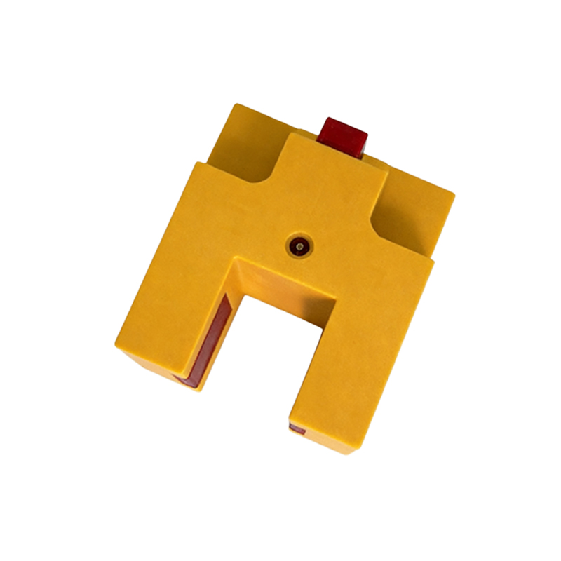
Core Components and Electrical Interface
Understanding the hardware is crucial before programming. The emitter typically requires a DC power supply (e.g., 10-30 VDC) and has two wires. The receiver is more complex, featuring power (V+ and V-), at least one output signal wire, and often status indicator LEDs. The output can be NPN (sinking) or PNP (sourcing) transistor-based, or a relay contact. For programmable logic controller (PLC) integration, a digital input (DI) module is standard. Some advanced sensors offer programmability via pushbuttons, teach-in functions, or IO-Link digital communication, allowing parameter adjustment like light-on/dark-on mode, output delay timers, and sensitivity without manual potentiometers. Always consult the datasheet for wiring diagrams, voltage ranges, and output current limits to ensure compatibility with your controller.
Basic PLC Ladder Logic Programming
Integrating a through-beam sensor with a PLC involves simple digital input reading. First, wire the sensor's output to a PLC input point (e.g., I0.0). If using a PNP sensor, connect its output to the PLC input and the common to DC negative. For an NPN sensor, connect the output to the PLC input and the common to DC positive. In ladder logic, the sensor's input contact is used as a condition. For a "dark-on" sensor (output activates when beam is blocked), use a normally open (NO) contact instruction referencing the input address. When the beam is interrupted, the contact closes, energizing a coil or triggering subsequent logic for counting, stopping a conveyor, or activating a reject mechanism. Always include debouncing logic or use the PLC's hardware filter to prevent false triggers from rapid vibration or debris.
Implementing Advanced Functions: Counting and Timing
Beyond simple detection, through-beam sensors excel in applications requiring counting or precise timing. For object counting on a conveyor, program a rising-edge detection instruction triggered by the sensor's input. Each beam break increments a counter register. To prevent double-counting, incorporate a timer or a second sensor for verification. Timing functions are vital for measuring object length or speed. Use the sensor's signal to start and stop a high-speed timer within the PLC. The elapsed time, combined with known conveyor speed, calculates object length. For speed measurement, time the gap between two fixed sensors. Many modern PLCs offer dedicated high-speed counter (HSC) modules for accurate counting of rapid pulses beyond the scan cycle limit, which is essential for high-speed packaging or assembly lines.
Error Handling and Diagnostic Programming
Robust programming must account for potential failures. Through-beam sensors can experience alignment issues, lens contamination, or cable faults. Program diagnostic routines by monitoring the sensor's signal stability. For instance, if an object is expected to pass within a maximum time window, use a timer that triggers an alarm if the beam remains unbroken for too long, indicating a jam. Conversely, if the beam stays broken beyond a set time, it may signal a fallen object. Utilize the PLC's system diagnostics or, with IO-Link sensors, read detailed status data (like signal strength, temperature, contamination level) directly into the program. Implementing a periodic heartbeat check—where the PLC expects a state change within a known cycle—can confirm sensor health. Always include manual override and alarm acknowledgment functions in the HMI interface.
Optimization and Best Practices
To ensure long-term reliability, optimize the program and installation. Shield the sensor from ambient light interference, especially sunlight, which can swamp the receiver. In the program, use hysteresis or a minimum break duration to avoid flickering outputs from small, fast-moving debris. For critical applications, implement redundancy using two sensors in a voting logic. Regularly log operational data, such as count totals or error frequencies, to predictive maintenance schedules. When setting sensitivity or response time via programming tools (like vendor software for IO-Link), balance speed with noise immunity. Finally, document the program thoroughly, noting input addresses, sensor modes, and alarm thresholds, to facilitate future troubleshooting and maintenance by other engineers.