Introduction to Photoelectric Sensor Fault Indicators
Photoelectric sensors are widely used in industrial automation for detecting objects, measuring distances, and ensuring process control. A critical component of these sensors is the fault indicator light, which provides immediate visual feedback on the sensor's operational status. Typically, these indicators use LED lights in colors such as green, red, or amber to signal normal operation, detection events, or errors. Understanding the meaning of these lights is essential for maintenance personnel to quickly diagnose issues, minimize downtime, and maintain system efficiency. This guide delves into the common fault indications, their causes, and troubleshooting steps to help engineers and technicians effectively manage sensor performance.
Common Fault Indicator Patterns and Their Meanings
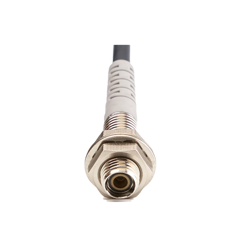
Fault indicators on photoelectric sensors follow specific patterns to convey different statuses. A steady green light usually indicates that the sensor is powered and functioning correctly without any detected objects. A blinking green light might signal that the sensor is in a teach-in mode or is actively detecting objects. A steady red light often points to a fault, such as a wiring error, short circuit, or overload condition. A blinking red light can indicate issues like sensor misalignment, contamination on the lens, or an out-of-range detection scenario. Some advanced sensors use amber lights for warnings, such as nearing the end of the sensor's lifespan or minor environmental interferences. Recognizing these patterns allows for swift identification of problems, reducing the need for extensive diagnostic tools.
Causes of Fault Indicator Activation
Several factors can trigger fault indicators on photoelectric sensors. Electrical issues are common, including incorrect voltage supply, loose connections, or damaged cables that lead to power fluctuations. Environmental factors, such as dust, moisture, or extreme temperatures, can obstruct the sensor's lens or affect its internal components, causing false readings or failures. Mechanical problems, like misalignment due to vibration or physical impact, may disrupt the sensor's beam, leading to detection errors. Additionally, sensor aging or component wear over time can result in inconsistent performance, signaled by fault lights. Understanding these root causes helps in implementing preventive measures, such as regular inspections and proper installation practices, to avoid recurring faults.
Troubleshooting Steps for Fault Indicators
When a fault indicator lights up, systematic troubleshooting can resolve most issues efficiently. First, check the power supply and wiring connections to ensure they match the sensor's specifications and are secure. Inspect the sensor's lens for dirt or obstructions, cleaning it gently with a soft cloth if necessary. Verify the sensor's alignment by testing it with a known object in its detection range; adjustments may be needed to optimize the beam path. Review the sensor's settings, such as sensitivity or timing parameters, as incorrect configurations can trigger false faults. If the issue persists, consult the manufacturer's manual for error codes or use diagnostic tools to measure output signals. In cases of persistent faults, consider replacing the sensor or contacting technical support for further assistance.
Preventive Maintenance and Best Practices
To minimize fault indicator activations, adopt preventive maintenance routines and best practices. Regularly clean sensor lenses and housings to prevent buildup from dust or debris that could interfere with detection. Ensure proper installation by mounting sensors securely in stable environments, away from excessive vibration or temperature extremes. Use protective enclosures or coatings in harsh conditions to shield sensors from moisture and chemicals. Periodically test sensor performance with calibration checks to verify accuracy and adjust settings as needed. Train personnel on interpreting indicator lights and basic troubleshooting to enable quick responses. By integrating these practices, industries can enhance sensor reliability, extend operational life, and reduce unexpected downtime in automation systems.
Conclusion and Key Takeaways
The fault indicator light on photoelectric sensors serves as a vital tool for maintaining industrial automation efficiency. By interpreting light patterns accurately, technicians can diagnose issues ranging from electrical faults to environmental interferences. Common causes include wiring problems, contamination, and misalignment, which can often be addressed through straightforward troubleshooting steps like cleaning, realigning, or checking power sources. Emphasizing preventive maintenance, such as regular inspections and proper installation, further reduces fault occurrences. Ultimately, a proactive approach to understanding and managing these indicators ensures smoother operations, cost savings, and improved safety in automated processes. Stay informed about your specific sensor models and updates to leverage their full potential in diverse applications.