Understanding the Green LED Indicator
The green LED on a photoelectric sensor is a critical diagnostic tool. It typically signifies normal operation, indicating that the sensor has power, is functioning correctly, and is in its "on" state or receiving a valid signal from its receiver. When this light fails to illuminate, it signals an interruption in the intended operational chain. This absence can stem from simple issues like incorrect wiring or complex internal component failures. Technicians and engineers rely heavily on this visual cue for quick system status checks. Understanding its specific meaning for your sensor model is the first step, as some sensors use a green light to indicate output activation, while others use it for a stable power or "ready" status. Always consult the specific datasheet or manual for the definitive interpretation.
Initial Power Supply Checks
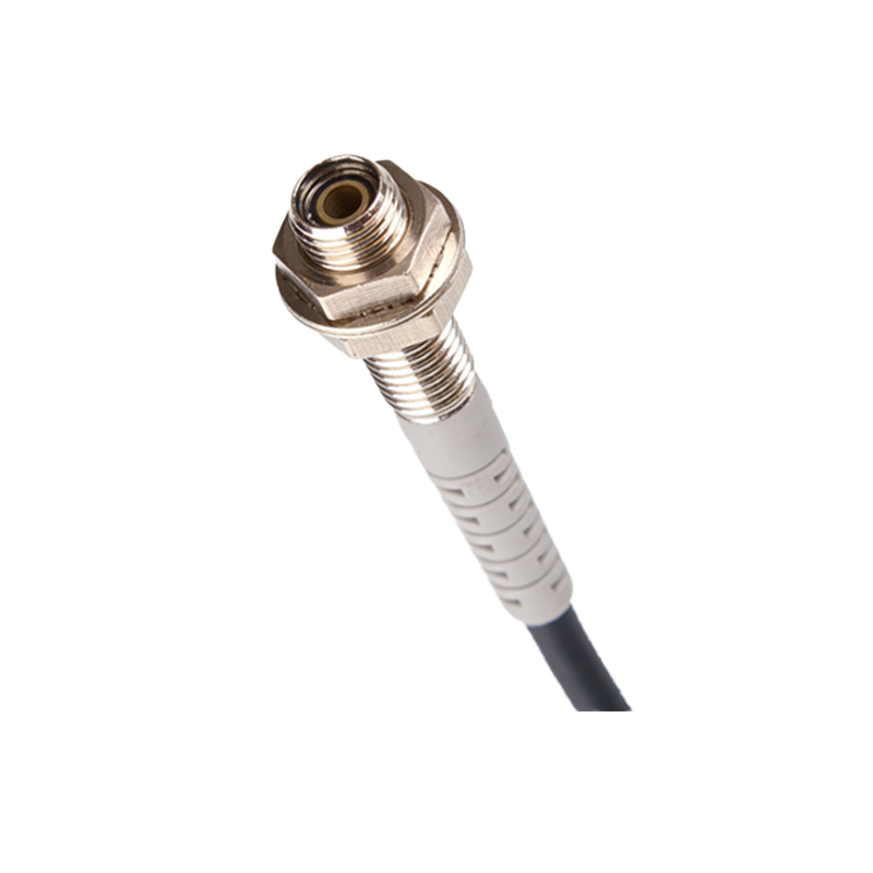
Begin all troubleshooting by verifying the power supply, as it is the most common culprit. Ensure the sensor is connected to the correct voltage as specified on its nameplate. Use a multimeter to measure the voltage directly at the sensor's power terminals. Confirm that the polarity is correct for DC sensors; reversing positive and negative leads is a frequent error. Check for stable voltage without significant drops or fluctuations, especially under load. Inspect the fuse or circuit breaker supplying power to the sensor circuit. Also, examine the wiring for any loose connections, corrosion, or physical damage at the terminal blocks, connectors, and along the cable run. A poor ground connection can also prevent proper operation.
Wiring and Configuration Verification
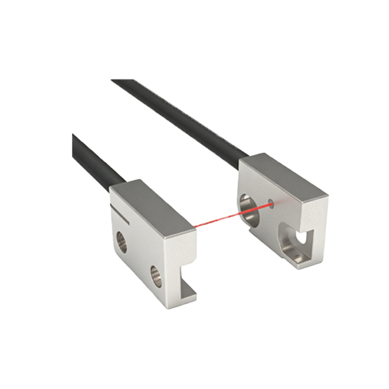
Incorrect wiring or configuration settings can prevent the green light from turning on. For a three-wire DC sensor, verify the brown wire is connected to positive (+V), the blue wire to negative (0V), and the black wire is the output. For AC sensors, ensure correct line and neutral connections. Next, examine the sensor's operating mode. Is it set to Light-ON or Dark-ON? In Light-ON mode, the output (and often the green light) activates when the receiver detects the light beam. In Dark-ON, the opposite is true. An incorrectly set mode might show no green light because the condition for activation is not met. Also, check for any teach-in or configuration buttons that may have been accidentally pressed, altering the sensing parameters.
Sensor Alignment and Optical Path Inspection
For through-beam and retro-reflective sensors, precise alignment is paramount. Even a slight misalignment can cause the receiver to not detect the light beam, resulting in no output signal and consequently, no green indicator. Visually inspect the alignment of the emitter and receiver. Use the sensor's built-in alignment aid, often a red beam visible for setup, to ensure the receiver is directly in the path. For diffuse sensors, ensure the target is within the specified sensing range and that the surface reflectivity is suitable. Clean the lenses of both the emitter and receiver with a soft, lint-free cloth. Dust, dirt, oil, or condensation can completely block or scatter the light beam. Inspect for physical obstructions in the optical path.
Environmental and Interference Factors
Harsh environmental conditions can cause the green light to remain off. Extreme temperatures beyond the sensor's rated operating range can cause internal circuitry to malfunction. Exposure to excessive vibration or shock may damage internal components or loosen connections. Check for ambient light interference, particularly from strong sources like sunlight or welding arcs, which can swamp the receiver in a photoelectric sensor. For DC sensors, electrical noise from motors, drives, or solenoids can disrupt the sensor's electronics. Ensure proper shielding, grounding, and separation of power and signal cables. In wet or dusty environments, verify the sensor's ingress protection (IP) rating is adequate and that its housing has not been compromised.
Load and Output Circuit Testing
The problem may lie not with the sensor itself, but with the load it is controlling or the subsequent circuitry. If the sensor has a separate output indicator (sometimes an orange or yellow LED) that activates, but the green "power/ready" light does not, the issue may be internal. However, if you suspect the output is the green light's driver, test the output. Disconnect the sensor's output wire from the load (e.g., a PLC input, relay coil). Using a multimeter in voltage mode (for a switching output) or a dummy load like a resistor and meter, check if the output switches state when the sensing condition is met. A failed output transistor or circuit will not activate the green light. Also, ensure the load impedance is within the sensor's specifications; an overload can damage the output stage.
Internal Diagnostics and Final Steps
If all external checks pass—power is correct, wiring is sound, alignment is perfect, environment is controlled, and the load is tested—the issue likely resides within the sensor. Look for any signs of physical damage, overheating (discoloration), or burnt components. Some advanced sensors have diagnostic fault indicators via blinking LED patterns; consult the manual for blink code interpretations. As a final verification, substitute the suspect sensor with a known-good unit of the same model under identical conditions. If the new sensor works immediately, it confirms a failure of the original unit. Internal failures can include a degraded LED light source, failed receiver element, damaged power regulation circuitry, or a fault in the processing ASIC. In such cases, sensor replacement is the standard remedy.