Introduction to Pedal Photoelectric Sensors
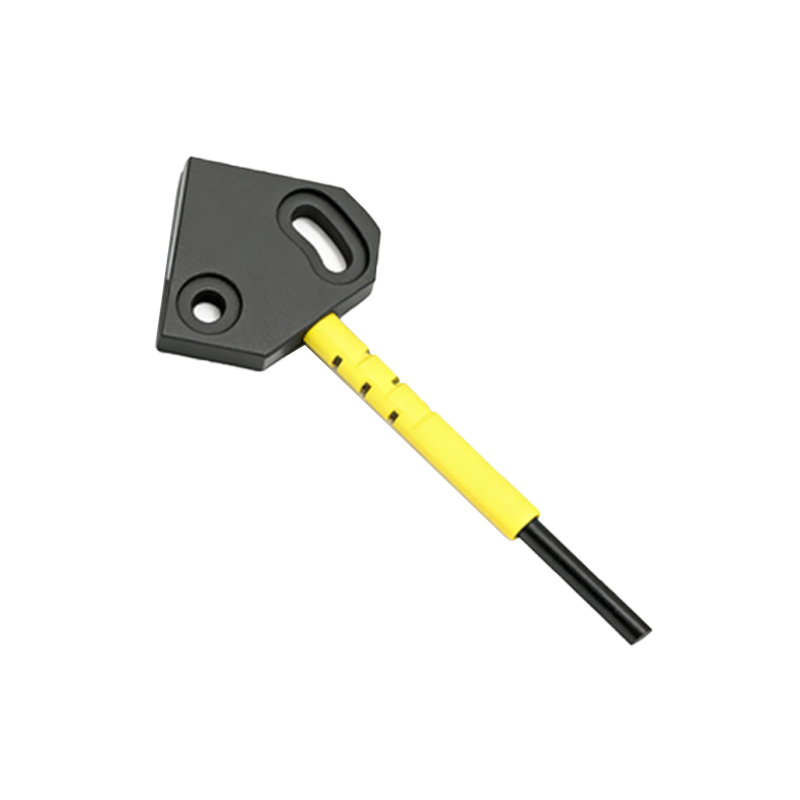
The photoelectric sensor embedded within the pedal assembly is a critical component for the safe and intuitive operation of modern self-balancing scooters, often referred to as hoverboards or electric balance boards. Unlike mechanical switches, these sensors provide a non-contact, wear-free method of detecting user presence. The core principle involves an infrared (IR) light emitter and a photodetector, typically a phototransistor or photodiode, positioned on opposite sides of a designated gap within the pedal structure. When a user's foot is not present, the emitted IR light beam travels unimpeded across this gap and is received by the detector, generating a specific signal state interpreted by the central control unit (CCU) as "rider off." Upon foot placement, the shoe obstructs the IR beam, causing a significant change in the detector's output. This state change is instantly communicated to the CCU, signaling "rider on" and enabling the motor system to activate and respond to user lean for propulsion and balance.
Technical Working Principle and Signal Processing
The operational integrity of the pedal sensor relies on a modulated IR signal to combat ambient light interference, a common challenge in photoelectric applications. The emitter is driven by a pulsed current, creating a modulated light beam at a specific frequency (e.g., several kilohertz). The corresponding detector circuit is tuned to respond only to signals at this modulation frequency, effectively filtering out constant or slowly varying light from the sun or indoor lighting. The detector's output is a weak analog signal, which is then amplified and conditioned by an operational amplifier circuit. Subsequently, a comparator circuit converts this conditioned signal into a clean, digital high or low logic signal suitable for the microcontroller's input pin. This digital signal provides a definitive, noise-resistant indication of beam status, ensuring reliable detection regardless of environmental brightness or the color and material of the user's footwear.
Integration with Vehicle Control Systems
The digital "foot-on-pedal" signal is a fundamental enabling input for the scooter's main controller. The CCU's firmware continuously polls the status of both left and right pedal sensors in a rapid loop. Only when both sensors confirm rider presence does the controller exit a standby or safety-lock mode and engage the gyroscope and accelerometer data for balance calculation. This two-sensor logic is a crucial safety feature, preventing accidental activation. Furthermore, the sensor data is integral to startup procedures. Many models require the rider to step onto both pedals simultaneously on a level surface for a successful calibration and startup sequence. During operation, a sudden loss of signal from one sensor (e.g., if a foot slips off) triggers an immediate safety protocol, often involving gradual motor power reduction, audible alarms, and tilting the pedal upward to prompt the rider to dismount safely, thereby preventing a potential crash.
Common Failure Modes and Diagnostic Procedures
Despite their solid-state design, pedal photoelectric sensors are susceptible to certain failure modes. The most prevalent issue is contamination; dust, mud, or moisture accumulation on the emitter or detector lenses can attenuate or scatter the IR beam, leading to intermittent or complete failure of detection. Physical damage from impact or water ingress into the pedal housing can also compromise the electronic components or their connections. Diagnosing a suspected sensor fault typically begins with a visual inspection of the lens windows for obstructions. Using a multimeter, a technician can check for proper voltage supply to the sensor module. The most conclusive test involves using an oscilloscope or a logic probe to observe the digital output signal while manually blocking and unblocking the sensor gap with an opaque object. A failure to toggle states indicates a faulty sensor assembly, damaged wiring harness, or a problem with the signal conditioning circuitry on the main control board.
Maintenance, Cleaning, and Replacement Guidelines
Preventive maintenance is key to ensuring long-term sensor reliability. Regular cleaning of the pedal surfaces and, more importantly, the small sensor windows (usually visible as small transparent or dark plastic sections on the pedal's inner side) with a soft, dry cloth is recommended. Avoid using harsh chemicals or high-pressure water sprays directly on these areas. If moisture exposure occurs, allowing the unit to dry thoroughly in a well-ventilated area before use is essential. When replacement is necessary, it is crucial to source an identical or manufacturer-approved sensor module. The replacement process involves carefully opening the pedal housing, disconnecting the old sensor's connector, and installing the new unit, ensuring it is seated correctly in its mounting bracket to maintain precise optical alignment. Post-replacement, a functional test verifying that the scooter only activates with both pedals occupied is mandatory before returning the device to the user.
Advancements and Future Trends in Detection Technology
While current IR beam-break sensors are cost-effective and reliable, the industry is exploring more advanced solutions. One emerging trend is the integration of capacitive sensing pads within the pedal surface. These pads detect the proximity or touch of a conductive object (like a human foot) through changes in an electrical field, offering potential advantages in sealing against water and dust as they require no external aperture. Another area of development is sensor fusion, where data from the basic presence sensor is combined with input from a pressure-sensitive resistor (FSR) matrix. This could allow the controller to not only detect presence but also gauge foot positioning and weight distribution, enabling more nuanced control schemes or advanced safety features, such as detecting incorrect foot placement and providing haptic feedback through the pedals to correct the rider's stance.