Introduction to OSM70 Photoelectric Sensors
The OSM70 series represents a versatile line of photoelectric sensors designed for precise object detection across diverse industrial environments. These sensors utilize advanced optical technology to detect the presence, absence, or position of objects without physical contact. Known for their robust construction and reliable performance, OSM70 sensors are integral components in automation systems, packaging machinery, material handling, and assembly lines. This guide provides a comprehensive setup and configuration manual to ensure optimal sensor deployment and operation.
Unpacking and Initial Inspection
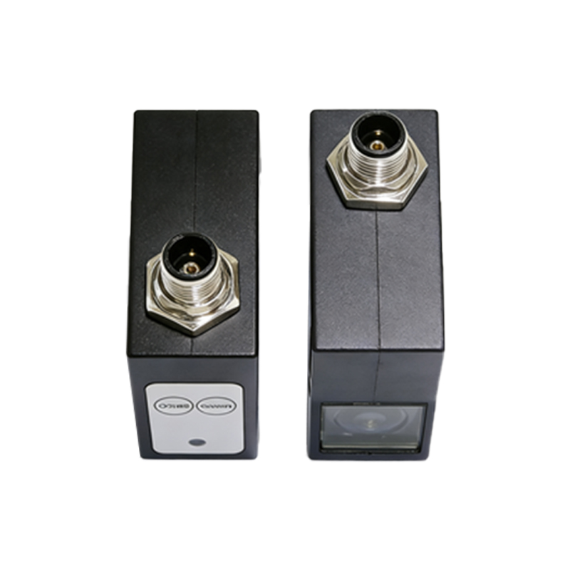
Upon receiving the OSM70 sensor, carefully unpack all components from the shipping container. The standard package typically includes the sensor unit, mounting brackets, connector cables, and an instruction manual. Conduct a thorough visual inspection for any signs of physical damage incurred during transit. Verify the model number on the sensor housing matches your order specifications. Ensure all necessary accessories are present before proceeding to the installation phase to avoid operational delays.
Mounting and Mechanical Installation
Select an appropriate mounting location that provides a clear, unobstructed path between the sensor's emitter and receiver. For through-beam models, align the transmitter and receiver units precisely on opposite sides of the detection area. For retro-reflective or diffuse models, ensure the target object will pass within the specified sensing range. Use the provided brackets to securely fasten the sensor to a stable surface, minimizing vibration exposure. Maintain proper clearance from other machinery and avoid locations with excessive dust, moisture, or temperature extremes beyond the sensor's rated specifications.
Electrical Wiring and Connection
Always disconnect power from the control system before initiating any wiring procedures. The OSM70 sensor typically features a standard M12 connector or terminal block for electrical connections. Refer to the sensor's datasheet for the specific pin configuration. Connect the brown wire (or pin) to the positive DC supply voltage (typically 10-30 VDC), and the blue wire (or pin) to the common ground (0V). The black wire (or pin) usually serves as the output signal line, which should be connected to the PLC input or control device. Ensure all connections are tight and properly insulated to prevent short circuits or intermittent operation.
Operating Mode Selection and Configuration
The OSM70 sensor often includes a configuration mode selectable via a built-in DIP switch or push-button interface. Common operating modes include Light-On (output activates when light is received) and Dark-On (output activates when light is blocked). For sensors with background suppression or foreground suppression capabilities, select the appropriate mode based on your application's requirements. Some advanced models may feature teach-in functionality, allowing automatic adjustment of the sensing threshold by pressing a button while the target object is present. Consult the specific model's manual for detailed mode selection procedures.
Sensitivity Adjustment and Alignment
Fine-tuning the sensitivity is crucial for reliable detection. Locate the sensitivity potentiometer or digital adjustment interface on the sensor housing. For through-beam and retro-reflective types, adjust the sensitivity so the sensor reliably detects the target object while ignoring smaller debris or environmental interference. For diffuse reflective sensors, adjust the sensing distance threshold to distinguish between the target and the background. Use the sensor's stability indicator (often an LED) to guide adjustments—typically, the LED should remain stable when the target is present and absent during normal conditions. For precise alignment of through-beam pairs, use the alignment aids or indicators on the sensor housing.
Output Configuration and Timing Functions
Configure the sensor's output type to match your control system requirements. The OSM70 typically offers options for NPN (sinking) or PNP (sourcing) transistor outputs. Some models may include analog outputs or IO-Link digital communication for advanced diagnostics and parameter setting. If the sensor includes adjustable timing functions like ON-delay or OFF-delay, set these parameters to filter out brief signal fluctuations or to synchronize with machine cycles. Ensure the output load current does not exceed the sensor's maximum rating to prevent damage to the internal circuitry.
Diagnostic Indicators and Troubleshooting
The OSM70 sensor is equipped with LED indicators that provide real-time status information. A power LED confirms voltage supply, while a stability or output LED indicates the detection state. Familiarize yourself with the blinking patterns described in the manual, as they often signify specific conditions like alignment issues, marginal signal strength, or fault states. Common troubleshooting steps include verifying power supply voltage, checking for optical obstructions, cleaning the lens surface, confirming sensing range limits, and inspecting wiring integrity. For persistent issues, consult the fault diagnosis chart in the product documentation.
Maintenance and Operational Best Practices
To ensure long-term reliability, implement a regular maintenance schedule. Periodically clean the sensor lens with a soft, lint-free cloth to remove dust, oil, or condensation that could attenuate the light beam. Avoid using abrasive or chemical cleaners that could damage the optical surface. Check mounting hardware for tightness, especially in high-vibration environments. Monitor the sensor's performance over time and recalibrate sensitivity if environmental conditions or target characteristics change significantly. Keep a log of any adjustments or replacements for future reference and system audits.
Safety Considerations and Compliance
Always adhere to local and international electrical safety standards during installation and operation. Ensure the sensor's enclosure rating (e.g., IP67) is suitable for the environmental conditions of the application. Implement proper lockout/tagout procedures when servicing sensors integrated into machinery. The OSM70 sensor is designed for use in industrial control systems and should not be employed in safety-critical functions without additional protective circuits or redundancy. Verify that the sensor's use complies with relevant industry regulations and machine safety directives applicable to your region.