Understanding Slot-Type Photoelectric Sensors
A slot-type photoelectric sensor, often called a through-beam sensor, consists of two separate components housed in a single U-shaped body: an emitter on one side and a receiver on the other. The emitter projects a beam of light—typically infrared, red, or laser—across the open slot to the receiver. When an object passes through this slot, it interrupts the light beam, causing the sensor's output to change state. This simple yet reliable principle makes it ideal for detecting the presence, absence, or position of objects, counting items on a conveyor, or verifying the position of a machine part. Unlike diffuse or retro-reflective sensors, the slot-type design offers a self-contained, aligned system, eliminating the need for separate mounting and alignment of emitter and receiver units, which significantly reduces installation complexity.
Pre-Installation Planning and Considerations
Before mounting the sensor, thorough planning is essential for optimal performance. First, select a sensor with appropriate specifications for the application: consider the slot width to accommodate the target object, the required sensing distance (which is fixed by the slot depth), the light source type, and the output configuration (PNP/NPN, NO/NC). The operating environment is critical; ensure the sensor's ingress protection (IP) rating is suitable for conditions involving dust, moisture, or washdowns. For high-vibration areas, choose models with robust housing. Verify the electrical requirements, including supply voltage (commonly 10-30V DC) and load current, match your control system. Finally, plan the mounting location to ensure the target object will reliably pass through the center of the slot and that the sensor body will not be subjected to physical impact or stress.
Mechanical Mounting Procedures
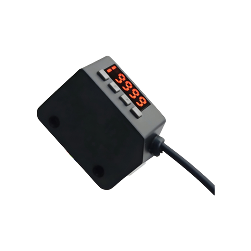
Secure mounting is fundamental to reliable operation. Most slot sensors feature mounting holes on the base or sides. Use the provided screws or appropriate fasteners to attach the sensor to a stable bracket or machine frame. Avoid over-tightening, as this can distort the housing and affect alignment. The sensor must be mounted rigidly to prevent movement from vibration or accidental contact. Ensure there is adequate clearance around the sensor for the target object and for maintenance access. The mounting surface should be flat and clean. For applications involving small or transparent objects, consider using mounting brackets that allow for fine positional adjustment to precisely center the object in the slot. Always follow the manufacturer's specified mounting orientation and clearances.
Electrical Wiring and Connection
Correct electrical installation ensures safe and stable operation. Begin by disconnecting power to the circuit. Refer to the sensor's datasheet for the wiring diagram, which typically details connections for the power supply (brown wire for +V, blue wire for 0V), the output signal (black wire), and possibly a separate output common. Use shielded cable in electrically noisy environments, grounding the shield at the controller end only. Keep sensor cables away from power lines and motor leads to minimize electromagnetic interference. For sensors with teach-in or diagnostic functions, connect any necessary interface wires. After wiring, perform a visual inspection for loose strands or poor connections. Use conduit or cable carriers in harsh environments to protect the wiring.
Alignment and Functional Testing
While the internal emitter and receiver are pre-aligned, the overall system alignment—ensuring the target breaks the beam correctly—is crucial. After powering the system, observe the sensor's indicator LED. A steady or blinking LED usually indicates normal operation and beam reception. Pass a standard target object through the slot. The output indicator should change state reliably. Test with the actual application object at the expected speeds. For counting applications, verify the sensor triggers consistently without double-counting due to object bounce. If the sensor has sensitivity adjustment, use it to fine-tune performance for challenging targets like glossy or dark-colored objects. Test the sensor under minimum and maximum expected environmental conditions, such as temperature extremes or varying ambient light.
Troubleshooting Common Installation Issues
Several common problems can arise post-installation. If the sensor does not respond, first verify power supply voltage and polarity. Check all electrical connections. If the output is constantly activated or never activates, the beam might be obstructed by dirt, debris, or condensation inside the slot. Clean the optical windows carefully with a soft, lint-free cloth. Misalignment due to mounting stress or impact can cause intermittent operation; re-check the mounting stability. Electrical noise can cause erratic behavior; ensure proper shielding and grounding. For false triggers, investigate if reflective surfaces near the slot are bouncing light back to the receiver or if ambient light (like sunlight) is overpowering the sensor's modulated light source. Always consult the manufacturer's troubleshooting guide.
Maintenance and Best Practices
Regular maintenance ensures long-term reliability. Establish a periodic inspection schedule to check for physical damage, loose mounting hardware, and accumulation of dirt, oil, or metal chips on the optical faces. Clean the lens as needed. Inspect cables for wear or damage. In harsh environments, consider using protective covers or air blow-off devices to keep the slot clear. Log sensor performance data to identify gradual degradation. Keep spare sensors on hand for critical applications to minimize downtime. Adhere to best practices: never modify the sensor housing, use only recommended cleaning agents, and always follow lock-out/tag-out procedures before performing any maintenance. Proper installation and care maximize the sensor's operational life and system uptime.