Introduction to Proximity Sensor Testing
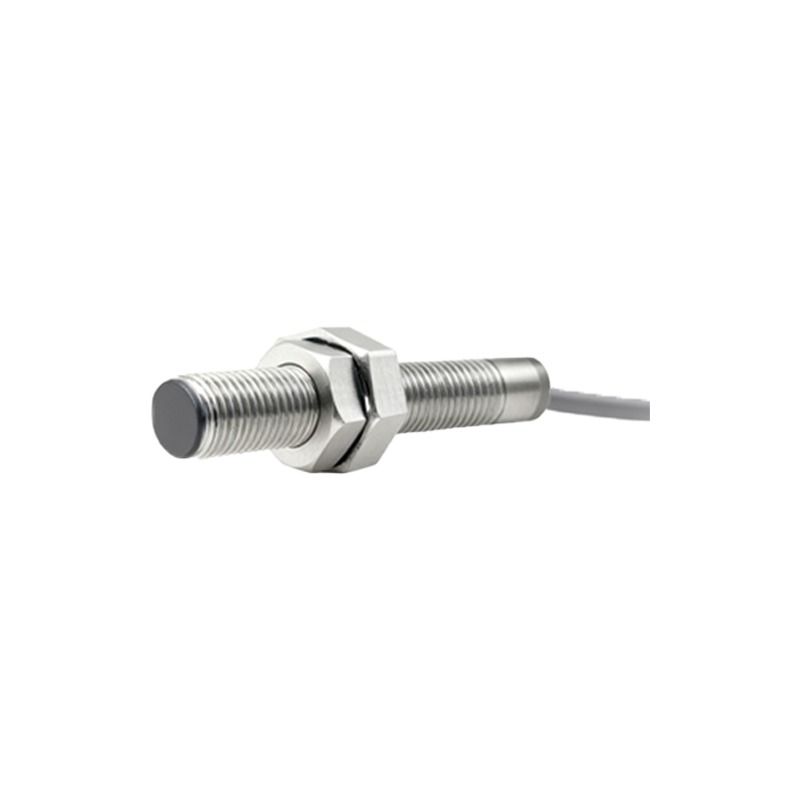
In the realm of industrial automation and control systems, proximity sensors are indispensable components. They detect the presence or absence of objects without physical contact, enabling critical functions in machinery, robotics, and safety systems. However, the reliability of these sensors is paramount. A single faulty sensor can lead to production downtime, safety hazards, or product defects. This underscores the necessity for robust and efficient testing methodologies. A well-designed test fixture is not merely a convenience; it is a fundamental tool for quality assurance, production validation, and R&D verification. This guide delves into the key principles and practical considerations for designing an effective proximity sensor test fixture.
Core Design Objectives and Requirements
The primary goal of a test fixture is to simulate real-world operating conditions in a controlled, repeatable manner. Key design objectives include accuracy, repeatability, speed, and versatility. The fixture must accurately position the test target relative to the sensor under test (SUT) to verify its specified sensing distance, or "switching point." Repeatability ensures that consecutive tests yield identical results, which is crucial for statistical process control. Speed is vital for high-volume production environments where throughput is a key metric. Finally, versatility allows the fixture to accommodate different sensor models, mounting styles, and target materials with minimal changeover time. Defining these requirements upfront is critical for a successful design.
Mechanical Design and Actuation
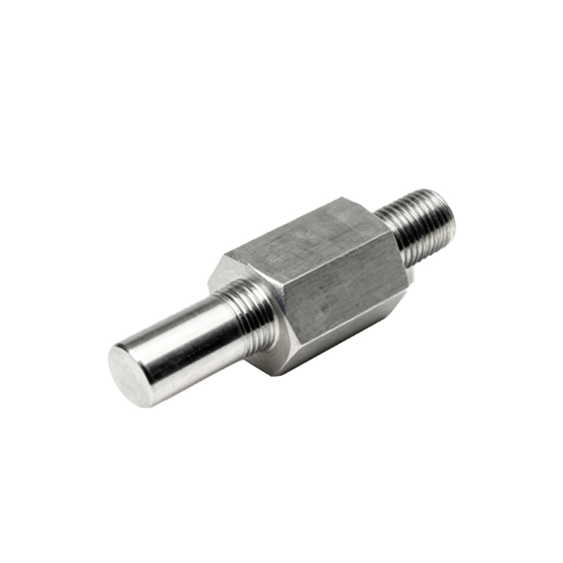
The mechanical subsystem forms the backbone of the fixture. It typically consists of a rigid base plate, a precise linear motion system, and a target mounting assembly. Ball screws or precision linear guides driven by stepper or servo motors are preferred for their accuracy and programmability. The choice of actuator depends on the required resolution, speed, and force. The target, which mimics the object the sensor will detect, must be made of the correct material (e.g., mild steel for inductive sensors, any material for capacitive sensors) and have standardized dimensions as per sensor datasheets. Vibration damping and structural rigidity are essential to prevent measurement errors induced by mechanical resonance or deflection.
Electrical Interface and Signal Conditioning
The electrical design focuses on interfacing with the SUT and measuring its response. The fixture must provide the correct supply voltage (e.g., 10-30V DC) and current to the sensor. For 3-wire sensors, this means connecting the positive, negative, and signal output lines. The fixture's measurement circuit must reliably read the sensor's output state—whether it's a PNP/NPN transistor switch, a NO/NC relay contact, or an analog voltage/current signal. Opto-isolators or relay modules are often used to protect the fixture's control circuitry from electrical noise or voltage spikes from the sensor. Signal conditioning circuits may include pull-up/pull-down resistors, debouncing logic, and analog-to-digital converters for precise threshold measurement.
Control System and Software
Modern test fixtures are governed by programmable logic controllers (PLCs), microcontrollers (like Arduino or Raspberry Pi for prototypes), or PC-based control cards. The control system orchestrates the motion profile, monitors sensor signals, and logs test results. The software should implement a defined test sequence: move the target into position, allow for sensor response time, read the output state, compare it to the expected value, and record pass/fail criteria. Key parameters to test include the operating switching distance, release distance, hysteresis, and response time. A user-friendly human-machine interface (HMI) allows operators to select test programs, view real-time results, and generate test reports.
Calibration and Traceability
The accuracy of the fixture itself must be verifiable. Incorporating a calibration routine is essential. This often involves using a master sensor or a calibrated distance measurement device, such as a laser micrometer or a high-precision dial indicator, to establish a known reference point. The fixture's motion system is then adjusted or its software offset is corrected to align with this standard. All calibration activities should be documented to ensure traceability to national or international standards. Regular calibration schedules must be maintained to guarantee long-term measurement integrity and compliance with quality management systems like ISO 9001.
Safety and Ergonomic Considerations
Safety is non-negotiable. The fixture should include physical guards to prevent operator contact with moving parts. Emergency stop buttons must be prominently placed and hard-wired to cut power to actuators. Light curtains or area scanners can provide additional protection. From an ergonomic perspective, the fixture should facilitate easy loading and unloading of sensors. Quick-release clamps or pneumatic holders can speed up this process. The HMI should be positioned for comfortable viewing and operation. Proper cable management prevents tripping