Understanding Photoelectric Sensors for Cylinder Applications
Photoelectric sensors are indispensable components in industrial automation, particularly for detecting cylinder piston positions. These sensors operate by emitting a light beam—typically infrared, visible red, or laser—and detecting changes in the received light caused by the presence or absence of a cylinder's piston or flag. The core principle relies on the interruption or reflection of this beam. For cylinder position sensing, the most common configurations are through-beam and retro-reflective types. Through-beam sensors offer the longest sensing ranges and highest reliability, as they consist of separate emitter and receiver units. Retro-reflective sensors, which combine emitter and receiver in one housing and use a reflector, are more compact and easier to align but can be susceptible to interference from shiny surfaces. Selecting the correct sensor type is the foundational step, dictated by the cylinder's size, stroke length, required response time, and the environmental conditions of the application, such as the presence of dust, oil, or ambient light.
Critical Mounting Considerations and Alignment
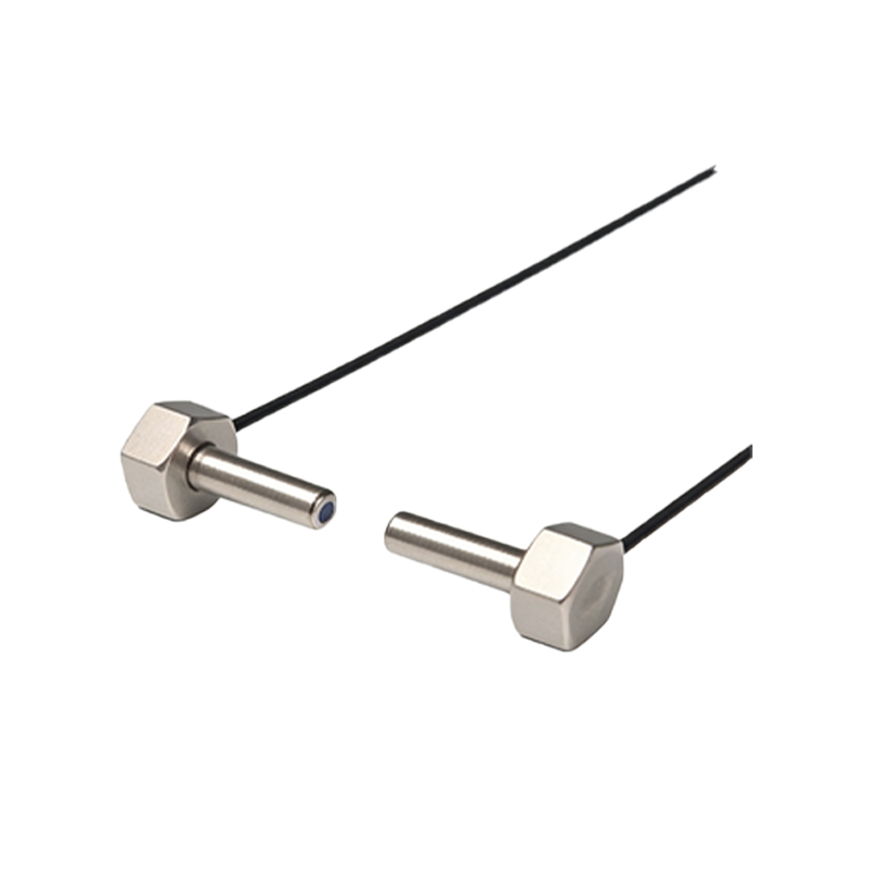
Proper mounting is paramount for reliable sensor operation. The primary goal is to ensure consistent and precise alignment between the sensor (and reflector, if used) and the target flag on the cylinder piston. Misalignment is the leading cause of sensor failure in these applications. For through-beam sensors, the emitter and receiver must be precisely opposite each other, with their optical axes perfectly collinear. Even a slight angular deviation can cause the beam to miss the receiver's detection area. Retro-reflective sensors must be aligned perpendicularly to the reflector's surface. Vibration and mechanical shock from the cylinder's operation can gradually shift mounts over time. Therefore, using robust, adjustable mounting brackets made from durable materials like anodized aluminum or stainless steel is essential. These brackets should allow for fine adjustments in multiple axes—horizontal, vertical, and rotational—to facilitate initial setup and compensate for any future drift. The mounting hardware must be securely tightened to the specified torque to prevent loosening.
Bracket Selection and Mechanical Integration
The mounting bracket acts as the critical interface between the sensor and the cylinder or machine frame. A well-designed bracket provides stability, precise adjustability, and protection. Common bracket styles include C-shaped clips that attach directly to the cylinder body, L-shaped arms that mount to a nearby surface, and specialized saddle clamps. The choice depends on the cylinder type (round body, square body, tie-rod) and available space. The bracket must hold the sensor firmly to prevent any movement relative to the cylinder's travel path. For applications with high cyclic rates or significant vibration, consider brackets with integrated damping or locking mechanisms. Furthermore, the bracket should position the sensor so that the target flag interrupts the beam cleanly and completely. The flag's design is equally important; it should be made of an opaque material with a straight, clean edge to create a sharp transition signal. The flag's travel must pass through the sensor's sensitive "spot" at the correct point in the cylinder stroke.
Electrical Wiring and Environmental Protection
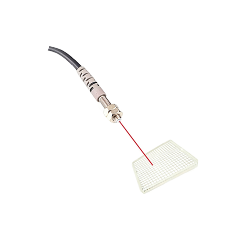
Secure mechanical mounting must be complemented by correct electrical installation. Most modern photoelectric sensors for cylinders use quick-disconnect M8 or M12 connectors, which simplify wiring and replacement. It is crucial to follow the manufacturer's wiring diagram for the specific output type (PNP/NPN, NO/NC) and supply voltage. Use shielded cables in electrically noisy environments, grounding the shield at the control panel end only to prevent ground loops. Cable management is often overlooked; the sensor cable must be routed away from moving parts, sharp edges, and high-temperature zones. Use cable ties, conduits, or flexible carriers to strain-relieve the connection point at the sensor. Environmental sealing is another key factor. Sensors should have an appropriate Ingress Protection (IP) rating (e.g., IP67 or IP69K) for the application. In dirty or wet conditions, ensure the connector is fully mated and sealed. For washdown environments in food and beverage processing, sensors and brackets must withstand high-pressure, high-temperature cleaning with corrosive chemicals.
Commissioning, Testing, and Maintenance Protocols
After physical installation, systematic commissioning ensures long-term reliability. First, power the system and observe the sensor's indicator LED. Manually cycle the cylinder slowly to verify that the sensor activates and deactivates at the exact desired positions. Use the sensor's built-in sensitivity potentiometer or teach-in function (if available) to set the optimal threshold, ensuring a stable signal with a sufficient margin against background interference. Document these settings. Implement a routine preventive maintenance schedule. Periodically inspect the sensor lens for accumulation of dirt, oil, or debris, and clean it with a soft cloth and appropriate cleaner. Check the tightness of all mounting hardware and the integrity of the bracket. Verify that alignment has not shifted by monitoring the signal stability during operation. Log any intermittent faults, as they often precede a complete failure. Keeping spare sensors and brackets on hand minimizes downtime in case of a failure.