Introduction to Slot-Type Photoelectric Sensors
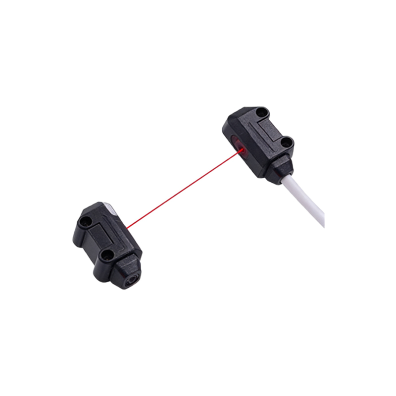
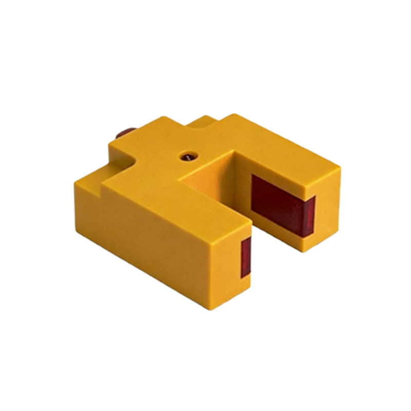
Slot-type photoelectric sensors, also known as through-beam sensors, are fundamental components in industrial automation. They consist of a matched emitter and receiver housed in a single U-shaped body, creating a precise optical slot. These sensors detect objects that interrupt the light beam passing through this slot. Common applications include object detection, counting, and position verification on conveyor lines, printing machinery, and automated assembly systems. Understanding their internal construction is crucial for maintenance, troubleshooting, and custom modifications. This guide provides a detailed, safe methodology for disassembling a typical industrial-grade slot sensor.
Essential Tools and Safety Precautions
Before beginning any disassembly, gather the necessary tools and prioritize safety. You will typically need a set of precision screwdrivers (Phillips and flathead), a set of hex keys or Allen wrenches, needle-nose pliers, and an anti-static wrist strap. Ensure the sensor is completely disconnected from its power source and any associated control circuitry. Allow the sensor to sit for several minutes if it has been in operation to dissipate any residual electrical charge. Work on a clean, well-lit, and static-free surface. Handle the internal optical components with extreme care to avoid contamination from skin oils or dust, which can permanently degrade performance.
Step 1: External Housing Removal
The first step involves accessing the internal components by removing the external housing. Most slot sensors are held together by small screws located on the sides or bottom of the unit. Carefully remove these screws using the appropriate screwdriver. Some models may use snap-fit or glued housings, requiring gentle prying with a flathead tool. Take note of the screw types and their locations for reassembly. As you separate the two halves of the housing, do so slowly and evenly to avoid putting stress on any internal wires or connectors that may be attached to the housing. Place the screws in a small container to prevent loss.
Step 2: Disconnecting Internal Wiring and PCBs
Once the housing is open, you will see the internal printed circuit board (PCB) and the wiring harness. The PCB is typically mounted to one half of the housing or a internal frame. Before proceeding, document or photograph the wiring connections. Note the color coding and terminal designations. Gently disconnect any wire connectors or de-solder the wires if they are directly soldered to the board. Use needle-nose pliers to carefully release any tension clips or cable ties securing the wires. The goal is to free the PCB assembly from the housing without damaging the delicate traces or components.
Step 3: Separating the Emitter and Receiver Modules
The core of the slot sensor is the aligned emitter (usually an infrared LED) and receiver (a phototransistor or photodiode). These are often housed in separate, precisely aligned modules within the arms of the U-shaped body. They may be press-fit, glued, or screwed into place. Identify the method of fixation. If screwed, remove the tiny mounting screws. If press-fit or glued, apply gentle, even pressure or a minimal amount of approved solvent to loosen the bond. It is critical to maintain the orientation of these modules; mark them with a non-permanent pen if necessary. Avoid touching the optical lenses directly.
Step 4: Inspecting and Cleaning Optical Components
With the modules separated, you can now inspect the optical elements. Look for any signs of damage, such as cracked lenses, scratched surfaces, or accumulated debris. Contamination is a common cause of sensor failure. Use compressed air or a soft, lint-free brush to remove loose dust. For stubborn dirt, lightly moisten a lens cleaning tissue or swab with isopropyl alcohol (90% or higher) and gently wipe the lens surface in a circular motion. Allow it to air dry completely. Inspect the LED and phototransistor chips on the PCB for any physical damage or discoloration.
Step 5: Reassembly and Functional Testing
Reassembly is essentially the reverse process of disassembly. Begin by carefully reinstalling the cleaned emitter and receiver modules, ensuring perfect alignment as per your earlier markings. Reconnect the wiring to the PCB, double-checking all connections against your documentation or photos. Secure the PCB back into its mounting position. Before closing the housing, it is advisable to perform a preliminary test. Temporarily connect the sensor to power and observe its indicator LED while passing an object through the slot. If functional, proceed to seal the housing by reinstalling all screws firmly but without over-tightening. Conduct a final operational test in its intended application to verify sensitivity and alignment.
Common Pitfalls and Troubleshooting Tips
A common mistake is misaligning the optical modules during reassembly, leading to reduced sensing range or complete failure. Always use alignment marks. Over-tightening screws can crack plastic housings or strip threads. Applying excessive force when prying open housings can damage internal clips and latches. If the sensor fails after reassembly, re-check all electrical connections for continuity and correct polarity. Verify that no wires are pinched between housing halves. Persistent issues may indicate a damaged optical component that requires replacement rather than cleaning. Consult the manufacturer's datasheet for specific alignment tolerances and component specifications.