Distance laser sensors are widely used in industrial automation, robotics, and measurement systems due to their high precision and reliability. Understanding the principle behind these sensors is crucial for selecting the right device for specific applications. This article explains the working mechanism of distance laser sensors with the help of diagrams and descriptions, avoiding overly technical jargon to ensure clarity.
At the core of a distance laser sensor is the principle of triangulation or time-of-flight (ToF). Triangulation-based sensors are common for short to medium ranges, typically up to a few meters. In this method, a laser diode emits a focused beam of light toward the target object. The reflected light is then captured by a position-sensitive detector, such as a CCD or CMOS array. The diagram illustrates that as the distance to the target changes, the angle of the reflected beam shifts, causing the light spot to move on the detector. By calculating the position of this spot, the sensor's internal processor determines the exact distance. This process is highly accurate for reflective surfaces and is often used in quality control or assembly lines.
For longer distances, time-of-flight sensors are preferred. These sensors measure the time it takes for a laser pulse to travel to the target and back. The diagram shows a pulsed laser emitter and a receiver aligned in parallel. The sensor calculates distance using the formula: distance = (speed of light × time) / 2. This method is effective for ranges from several meters to hundreds of meters, making it suitable for applications like surveying, automotive safety, and drone navigation. Diagrams often highlight the compact design of ToF sensors, which integrate both emission and reception components into a single unit.
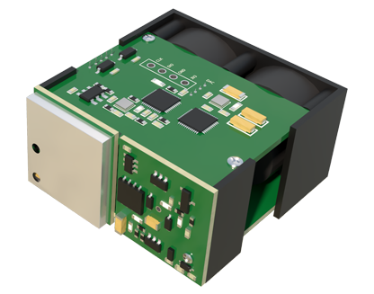
Key components depicted in principle diagrams include the laser source, optics, detector, and signal processing unit. The laser source, usually a Class 1 or Class 2 laser for safety, generates a coherent beam. Optics, such as lenses, focus the beam and collect reflected light. The detector converts light signals into electrical ones, which are then processed by algorithms to output distance data. Diagrams may also show environmental factors, like ambient light filters or protective housings, which enhance performance in real-world conditions.
Applications of distance laser sensors are diverse. In manufacturing, they monitor object positioning or thickness. In robotics, they enable obstacle detection and navigation. Diagrams often include real-world scenarios, such as a sensor mounted on a conveyor belt measuring product height, or integrated into an autonomous vehicle for collision avoidance. Understanding these diagrams helps users visualize how the sensor interacts with its environment, ensuring proper installation and calibration.
Maintenance and calibration tips are sometimes illustrated in supplementary diagrams. For instance, regular cleaning of optics prevents dust accumulation that could scatter laser beams. Calibration involves using known reference distances to adjust sensor readings, as shown in step-by-step visual guides. These practices extend sensor lifespan and maintain accuracy.
In summary, distance laser sensor principle diagrams serve as essential tools for comprehending their operation. By breaking down complex mechanisms into visual elements, they facilitate better decision-making in selection and implementation. Whether using triangulation or ToF, these sensors offer precise, non-contact measurement solutions across various industries. For optimal results, refer to manufacturer diagrams and guidelines tailored to specific models.