Understanding Photoelectric Sensor Wiring Fundamentals
Photoelectric sensors are indispensable components in modern industrial automation, providing reliable object detection across countless applications. Their operation hinges on emitting a light beam and detecting changes in the received light, which are then converted into an electrical output signal. The 3-wire configuration is among the most common and versatile wiring methods, offering a balance of simplicity and functionality. Unlike 2-wire sensors that are connected in series with the load, 3-wire sensors provide separate paths for power supply and the output signal. This design allows for more stable operation and easier integration into control systems. The three wires are universally color-coded: brown for the positive supply voltage, blue for the common negative or 0V, and a third color—typically black, white, or gray—for the output signal. This standardization is crucial for technicians and engineers during installation and troubleshooting, ensuring consistency and reducing wiring errors in complex control panels and machinery.
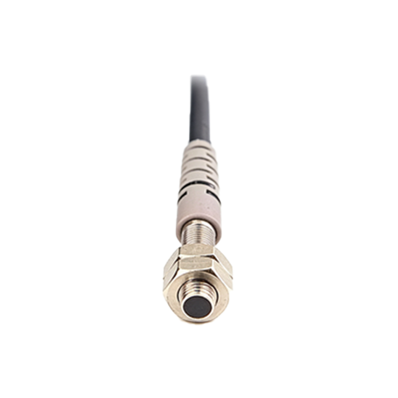
Detailed Breakdown of the 3-Wire Connection
A precise connection is vital for sensor performance and system safety. The brown wire must be connected to the positive terminal of the DC power supply. Common industrial voltages are 12-24V DC, but always verify the sensor's datasheet for its specific voltage range. The blue wire connects to the negative terminal of the same DC power supply, establishing the circuit's common ground or 0V reference. The third wire, the output, carries the switched signal. Its function depends on the sensor's output type: PNP (sourcing) or NPN (sinking). In a PNP sensor, the black output wire switches the positive voltage to the load. When the sensor is active, it connects the load to the positive supply. For an NPN sensor, the black wire switches the negative or 0V side. Here, the active sensor connects the load to ground. The load—a PLC input, relay coil, or indicator lamp—is then connected between the output wire and the opposite supply rail. Correctly identifying whether your sensor is PNP or NPN is the single most critical step before making any connections.
PNP vs. NPN Output Types: Selection and Wiring Implications
The choice between PNP and NPN output types is fundamental and depends on the control system's logic and the prevailing standards in your region. PNP (Positive-Negative-Positive) sensors, often associated with European electrical standards, source current to the load. In a typical PNP wiring scheme, the load is connected between the sensor's output wire (black) and the negative supply (blue). When the sensor detects an object, it provides a positive voltage signal to the load. Conversely, NPN (Negative-Positive-Negative) sensors, common in North America and Asia, sink current from the load. Here, the load is connected between the positive supply (brown) and the sensor's output wire (black). Upon detection, the NPN output connects the load to ground, completing the circuit. This distinction directly impacts how you interface the sensor with programmable logic controllers (PLCs). Most PLC digital input modules are designed to work with either type, but their internal circuitry requires the correct common connection (sinking or sourcing). Misunderstanding this can lead to a non-functional system or, worse, potential damage.
Step-by-Step Installation and Wiring Procedure
Following a systematic procedure ensures a safe and correct installation. First, completely disconnect power from the control panel or machine. Identify the sensor type (PNP/NPN) by checking the label or datasheet. Prepare the DC power supply, ensuring its voltage matches the sensor's requirements and its current rating exceeds the total draw of the sensor and the connected load. Strip the insulation from the sensor cable ends appropriately. Connect the brown wire to the positive (+) DC terminal. Connect the blue wire to the negative (-) or 0V DC terminal. For the output wire (e.g., black): if using a PNP sensor, connect one side of the load (e.g., PLC input terminal) to this wire, and the other side of the load to the negative supply (blue). If using an NPN sensor, connect one side of the load to the positive supply (brown), and the other side to this black output wire. Securely tighten all terminals. Before applying power, double-check all connections against a wiring diagram. Finally, restore power and test the sensor's operation by triggering its sensing field, verifying the output indicator LED and the response of the connected load.
Common Troubleshooting Techniques for 3-Wire Sensors
Even with correct installation, issues may arise. A structured troubleshooting approach is key. If the sensor shows no signs of life (no power LED illuminated), first verify voltage at the sensor's terminals between brown and blue wires using a multimeter. Incorrect polarity or voltage will prevent operation. If power is present but the output does not switch, confirm the output type (PNP/NPN) and the load connection. A common mistake is wiring an NPN sensor as if it were PNP, or vice versa. Check if the load is functional by testing it with a separate known-good source. Use the multimeter to measure the output voltage. For a PNP sensor, the output wire should go from near 0V to near supply voltage when activated. For an NPN, it should go from a high voltage (near supply) to near 0V. Also, consider environmental factors: ensure the sensing beam is not obstructed by dirt, and that the detected object is within the sensor's specified size, material, and distance parameters. Electrical noise in industrial settings can sometimes cause erratic behavior; ensure cables are routed away from high-power lines and consider using shielded cable if specified.
Best Practices for Reliable and Safe Operation
Adhering to industry best practices maximizes sensor lifespan and system reliability. Always implement proper electrical protection. Install a fuse or circuit breaker on the power supply line to protect against short circuits. For sensors in demanding environments, use conduit or cable carriers to protect wiring from physical damage, oils, and chemicals. Pay close attention to the sensor's datasheet specifications for parameters like switching capacity, residual current, and leakage current to ensure compatibility with delicate loads like PLC inputs. For long cable runs, account for voltage drop by calculating the wire gauge needed. When connecting multiple sensors, ensure the power supply has adequate current capacity for the total load. Finally, clearly label all wires and connections in the control panel. This not only aids during initial commissioning but is invaluable for future maintenance and modifications, saving significant time and reducing downtime during troubleshooting. Consistent application of these practices forms the foundation of a robust and maintainable automation system.