Introduction to Color Mark Sensing Technology
Color mark photoelectric sensors are specialized devices designed to detect specific color marks or differences in contrast on moving objects. Unlike standard photoelectric sensors that respond to the presence or absence of an object, these sensors are finely tuned to recognize a particular color or a specific light-to-dark contrast ratio. This capability is fundamental in numerous automation and packaging applications, such as label placement, product orientation, printing registration, and cut-to-length processes. The core principle involves emitting a focused beam of light onto a target surface and analyzing the intensity or spectral characteristics of the reflected light. By comparing this reflection to a pre-set reference value for the desired "mark," the sensor provides a precise output signal, triggering subsequent actions in a control system. The accuracy and reliability of this detection hinge not only on the sensor's internal electronics but also significantly on its physical shape and optical design, which determine how the light is projected and collected.
Key Shape Categories and Their Diagrams
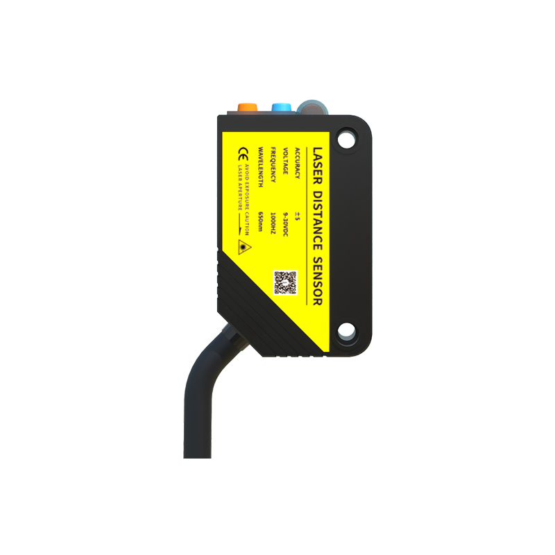
The physical form factor, or shape, of a color mark sensor is a critical determinant of its performance and suitability for a given application. These shapes are often depicted in technical diagrams that illustrate the sensor's housing, lens orientation, and beam path. The primary shape categories include cylindrical (barrel-style), rectangular (block-style), and slot-type sensors. Cylindrical sensors are the most common, featuring a threaded metal or polymer barrel. Diagrams for this type clearly show the front lens assembly and often indicate the sensing distance. Their compact, rugged design allows for easy mounting in tight spaces using standard nuts. Rectangular or block-style sensors present a different diagram, typically showcasing a flat, cuboid housing with the emitter and receiver windows on one face. This shape often facilitates side-by-side mounting for multi-sensor applications and may offer a wider sensing field. Understanding these diagrams is essential for selecting a sensor that fits the mechanical constraints of the machinery.
Through-Beam vs. Diffuse Reflective Shapes
The operating principle profoundly influences the sensor's shape diagram. Through-beam (or opposed) color mark sensors consist of two separate units: an emitter and a receiver. The diagram for this system shows two distinct housings, aligned opposite each other. The light beam travels from the emitter directly to the receiver. Detection occurs when the color mark on the passing object interrupts or alters this beam. This configuration offers the highest accuracy and longest sensing range but requires precise alignment of two components. In contrast, diffuse reflective (or proximity) sensors house both the emitter and receiver in a single unit. The diagram depicts a single housing with one or two windows. The sensor detects the mark based on the light reflected directly back from the target surface. The shape is generally more compact and simplifies installation, as only one device needs to be mounted. However, the sensing distance is shorter, and performance can be affected by the color and texture of the background material.
Focusing on Optical Path and Lens Design
A detailed shape diagram for a high-performance color mark sensor will include critical details about its optical path and lens design. This is often represented by dotted or solid lines within the housing outline, showing the path of the emitted and received light beams. Key features illustrated include the presence of a coaxial optical system, where the emitted light and the received light share the same central axis through a precisely engineered lens. This design minimizes the detection spot size, allowing for the sensing of very small or precise color marks. Diagrams may also show fixed-focus or adjustable-focus lenses. An adjustable-focus mechanism, sometimes depicted with a knurled ring on the sensor body, allows technicians to fine-tune the focal point for the exact working distance, optimizing the contrast signal from the mark against its background. This adjustability is crucial for handling varying material thicknesses or installation positions.
Housing Materials and Environmental Considerations
The external shape diagram also conveys information about the housing material and ingress protection (IP) rating, which are vital for environmental durability. Sensors designed for harsh industrial environments, such as washdown areas in food and beverage plants, are depicted with fully sealed, stainless steel housings or high-grade polymer casings with robust O-ring seals. The diagram might indicate the IP rating (e.g., IP67, IP69K) through standardized symbols. The shape itself can contribute to environmental resilience; a smooth, cylindrical housing with minimal crevices is easier to clean and less likely to trap debris. Furthermore, some specialized shapes include built-in mounting brackets, conduit entries, or indicator light windows in their design, all of which are detailed in the application diagrams to aid in planning the electrical and mechanical integration.
Integration and Mounting Diagram Analysis
Beyond the sensor itself, comprehensive shape diagrams include mounting details and dimensional drawings. These are engineering blueprints that provide exact measurements for the sensor body, thread size (e.g., M8, M12, M18), barrel length, and the position of mounting nuts or bolt holes. For rectangular sensors, the diagram specifies hole patterns for bracket attachment. Accurate analysis of these diagrams is non-negotiable for proper integration. It ensures the sensor can be physically installed in the available space and that the sensing beam will be correctly oriented toward the mark's path. Misalignment due to incorrect interpretation of mounting dimensions is a common source of application failure. Additionally, diagrams often show the location of the connection cable or plug (typically at the rear or side) and the status indicator LEDs, guiding the installer on orientation for visual diagnostics.
Selecting the Optimal Shape for Your Application
The final selection of a sensor shape is an engineering decision based on a synthesis of factors revealed by studying these diagrams. For high-speed web processing requiring detection of tiny registration marks, a small cylindrical sensor with a coaxial optical diagram is likely optimal. For detecting color marks on the side of large cartons where space is not constrained, a rectangular sensor might be preferred for its stable mounting base. In environments with heavy dust or spray, the diagram confirming a fully sealed, smooth housing is paramount. Engineers must cross-reference the mechanical constraints (available space, required sensing distance), the mark characteristics (size, color contrast), and the operational environment with the information provided in the sensor's shape and dimensional diagrams. This systematic approach ensures reliable detection, minimizes downtime, and optimizes the overall efficiency of the automated system.