Introduction to Non-Metallic Proximity Sensors
Non-metallic proximity sensors are specialized devices designed to detect the presence or absence of objects without physical contact, particularly targeting materials like plastics, wood, glass, and liquids. Unlike inductive sensors that rely on electromagnetic fields to sense metals, these sensors often utilize capacitive, ultrasonic, or optical principles to interact with non-conductive targets. Their operation hinges on changes in capacitance, sound wave reflection, or light beam interruption, making them versatile for diverse industrial applications where metal detection is insufficient. Common uses include level sensing in tanks, part detection on assembly lines, and position verification in packaging machinery. Understanding their fundamental technology is crucial before proceeding with installation, as it directly influences placement, calibration, and maintenance decisions.
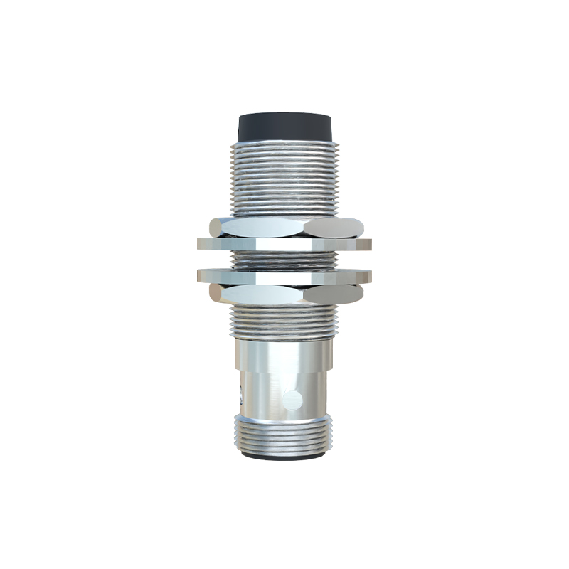
Pre-Installation Planning and Considerations
Effective installation begins with thorough planning to ensure optimal sensor performance. First, assess the application environment, including factors like temperature ranges, humidity levels, and potential exposure to dust, chemicals, or vibrations. Non-metallic sensors, especially capacitive types, can be sensitive to environmental changes, so selecting a model with appropriate ingress protection (IP) ratings is essential. Next, identify the target material's properties, such as dielectric constant for capacitive sensors or reflectivity for ultrasonic ones, as these affect detection range and reliability. Determine the required sensing distance, response time, and output type (e.g., PNP, NPN, analog). Additionally, consider electrical requirements like power supply voltage and current draw to match with control systems. Creating a detailed layout diagram can help visualize sensor placement relative to moving parts or other equipment, minimizing interference risks.
Mounting and Positioning Guidelines

Proper mounting is critical for accurate detection. Start by securing the sensor in a stable location using brackets or threaded mounts, ensuring it is firmly attached to avoid misalignment from vibrations. For capacitive sensors, maintain a consistent distance from the target—typically within the specified sensing range—and avoid placing them near metal objects or other sensors to prevent false triggers due to stray capacitance. Ultrasonic sensors require a clear, unobstructed path to the target; angle them slightly to reduce noise from reflective surfaces. Optical sensors need alignment of emitter and receiver components, with considerations for ambient light interference. In all cases, allow sufficient space for wiring and future adjustments. Test the positioning by moving the target through its expected path, verifying consistent detection without blind spots. Remember that non-metallic materials may have variable properties, so empirical testing under real conditions is advisable.
Wiring and Electrical Connections
Correct wiring ensures safe and reliable sensor operation. Begin by disconnecting power to the installation area to prevent electrical hazards. Refer to the sensor's datasheet for wiring diagrams, noting the color codes for power, ground, and output wires. Most non-metallic proximity sensors operate on low-voltage DC supplies (e.g., 10-30 VDC), so use shielded cables to reduce electromagnetic interference, especially in noisy industrial environments. Connect the wires to terminal blocks or connectors, ensuring tight connections to avoid voltage drops or signal loss. For capacitive sensors, some models feature sensitivity adjustments via potentiometers; set these according to the target material during wiring. Double-check polarities to prevent damage, and if using multiple sensors, avoid parallel wiring that could cause cross-talk. Finally, secure cables with clamps or conduits to protect them from physical wear and environmental exposure.
Calibration and Sensitivity Adjustment
Calibration fine-tunes the sensor for specific applications, enhancing detection accuracy. After installation, power on the system and observe the sensor's response to the target. For capacitive sensors, adjust the sensitivity potentiometer slowly until the sensor reliably detects the non-metallic material without triggering on background objects. This may involve balancing the dielectric influence of the target against environmental factors. Ultrasonic sensors often have settings for response time and temperature compensation; use these to account for air density changes. Optical sensors might require lens cleaning or alignment tweaks to maintain beam integrity. Document the calibration settings for future reference, and perform periodic checks, as material wear or environmental shifts can degrade performance over time. In complex setups, use programmable controllers to automate calibration routines for consistency.
Troubleshooting Common Installation Issues
Even with careful installation, issues may arise that affect sensor functionality. If the sensor fails to detect targets, verify power supply stability and wiring connections first. For intermittent operation, check for environmental interferences like temperature fluctuations or contaminant buildup on sensor faces. False triggers often stem from nearby objects or materials with similar properties; reposition the sensor or adjust sensitivity accordingly. Ultrasonic sensors might suffer from acoustic noise in busy environments—consider using models with frequency hopping or shielding. Optical sensors can be disrupted by ambient light;