Introduction to Photoelectric Sensor Control
Photoelectric sensors are fundamental components in modern industrial automation, utilizing light beams to detect the presence, absence, or distance of objects. Their operation hinges on the control circuitry that processes the light signal. This circuitry is responsible for converting the optical signal into a reliable electrical output that can interface with programmable logic controllers (PLCs), relays, or other control systems. The design and type of control circuit directly impact the sensor's performance, including its response time, accuracy, immunity to environmental interference, and output configuration. Understanding the various circuit topologies is crucial for selecting the right sensor for specific applications, such as object counting, level detection, or precision positioning.
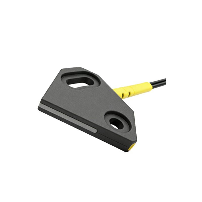
Basic On/Off (Digital) Output Circuits
The most common type of photoelectric sensor control circuit provides a simple digital (discrete) output. These circuits are designed to switch between two states: ON (logic high or closed contact) and OFF (logic low or open contact). Internally, a phototransistor or photodiode receives the modulated light beam. The circuit amplifies this signal and compares it to a predefined threshold set by a potentiometer or digital configuration. If the received signal strength exceeds the threshold (in a through-beam or retro-reflective sensor) or falls below it (in a diffuse sensor with background suppression), the output transistor switches. This output can be sinking (NPN) or sourcing (PNP), a critical distinction for compatibility with control system input cards. These robust circuits are the workhorses for basic detection tasks.
Analog Output and Measuring Circuits
For applications requiring distance measurement or grayscale analysis, photoelectric sensors employ analog output circuits. Instead of a simple threshold comparator, these circuits continuously measure the intensity of the reflected light. The received analog signal is linearly amplified and conditioned to produce a proportional output, typically 0-10V or 4-20mA. This allows the sensor to not only detect an object but also gauge its distance (in diffuse mode) or its transparency/reflectivity. The control circuitry here is more complex, often incorporating advanced filtering to ensure signal stability and linearity. Such sensors are invaluable in web tension control, diameter monitoring, and continuous level sensing of bulk materials.
Modulated LED and Synchronous Detection Circuits
To combat ambient light interference from factory lighting or sunlight, most industrial photoelectric sensors use a modulated light source and synchronous detection circuitry. The circuit drives the infrared or visible LED with a high-frequency pulsed signal. The receiver circuit is then tuned to only amplify signals oscillating at that specific frequency. This synchronous demodulation effectively filters out constant ambient light and low-frequency noise. This sophisticated control circuit design is what allows sensors to operate reliably in harsh, brightly lit environments, providing stable detection over long ranges and in the presence of dust or steam.
Background Suppression (BGS) Circuitry
Diffuse sensors with background suppression (BGS) feature specialized triangulation-based control circuits. These sensors use a position-sensitive detector (PSD) or a dual-receiver element. The circuitry analyzes the angle at which the reflected light returns, not just its intensity. By comparing the signals from the two receiver elements, the circuit can precisely determine if the reflection is from a near target or a distant background. It then provides a sharp digital output only for objects within a precise sensing window. This circuit design eliminates false triggers from objects beyond the set range, such as machinery behind the target or the factory floor.
Fiber Optic Amplifier Control Units
Fiber optic photoelectric sensors separate the sensing tip from the control electronics. The amplifier unit contains the core control circuit—the light emitter driver, receiver, processor, and output stage. The circuit is designed to work with the specific light loss characteristics of glass or plastic fibers. These amplifiers often feature multi-mode circuitry, allowing them to be configured for through-beam, diffuse, or retro-reflective operation via DIP switches or software. Their circuits include powerful sensitivity adjustment capabilities and often have dual digital outputs with independent teach-in functions for setting precise ON and OFF points, making them ideal for detecting minute objects or in extremely confined spaces.
Safety-rated and Muting Circuit Applications
In safety applications, such as guarding hazardous machine access points, safety-rated photoelectric curtains (light grids) use redundant and self-checking control circuits. These circuits continuously monitor the integrity of every emitter and receiver element, the power supply, and the output switching devices. Any fault, such as a damaged LED or a short circuit, forces the safety outputs (OSSDs) into a safe state (OFF). Similarly, muting circuits for automated guided vehicle (AGV) or conveyor palletizing stations use sequences of photoelectric sensors interfaced with a dedicated muting controller. This logic circuit temporarily disables the safety function in a controlled manner to allow material passage, relying on fail-safe design principles to prevent accidental deactivation.
Communication and Smart Sensor Interfaces
Modern photoelectric sensors integrate advanced control circuits with embedded microprocessors and communication interfaces. Beyond simple switching, these circuits enable IO-Link, AS-Interface, or Ethernet/IP connectivity. The circuit digitizes the sensor's analog signal at an early stage, allowing for detailed parameter setting (sensitivity, hysteresis, time delays) via software and the transmission of detailed diagnostic data (like signal strength, operating hours, or contamination warnings) back to the controller. This represents the evolution of the control circuit from a simple signal conditioner to an intelligent node in the Industrial Internet of Things (IIoT) ecosystem, enabling predictive maintenance and flexible production lines.