Introduction to Proximity Sensor Wiring
Proximity sensors are essential components in industrial automation, detecting the presence or absence of objects without physical contact. Proper wiring is critical for ensuring reliable operation and safety. This article provides a comprehensive guide to common wiring methods, supported by illustrative diagrams to aid understanding. Whether you are dealing with inductive, capacitive, or photoelectric sensors, the principles of wiring often share similarities in terms of power supply, output configuration, and connection to control systems.
Two-Wire DC Proximity Sensor Wiring
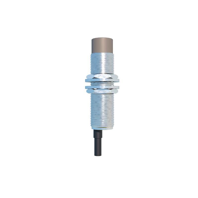
Two-wire DC proximity sensors are simple to install, as they connect directly in series with the load. The diagram typically shows a DC power source (e.g., 24V DC) linked to the sensor's brown wire (positive) and blue wire (negative), with the load (such as a relay or PLC input) placed between the sensor and ground. This setup reduces wiring complexity but may have limitations in leakage current, which can affect performance with low-power loads. Ensure the load impedance matches the sensor specifications to avoid malfunction.
Three-Wire DC Proximity Sensor Wiring
Three-wire DC sensors are widely used due to their reliability and separate power and output lines. A standard diagram includes a brown wire for positive power (e.g., +24V DC), a blue wire for negative or ground, and a black wire for the output signal. The output can be either NPN (sinking) or PNP (sourcing). For NPN wiring, the black wire connects to the load, which is then linked to positive voltage; for PNP, the black wire supplies current to the load connected to ground. Diagrams clearly depict these configurations, highlighting the importance of correct polarity to prevent damage.
Four-Wire DC Proximity Sensor Wiring
Four-wire DC proximity sensors offer dual outputs, such as both normally open (NO) and normally closed (NC) contacts, providing flexibility in control applications. The wiring diagram shows additional wires, often black and white, for separate output signals. These sensors typically include two power wires (brown and blue) and two output wires, allowing simultaneous switching for different circuits. This method is useful in complex systems where multiple actions are required based on sensor detection, and diagrams help visualize the connections to avoid cross-wiring errors.
AC Proximity Sensor Wiring Methods
AC proximity sensors, commonly used in high-voltage environments, require careful handling due to alternating current. A typical diagram illustrates a two-wire AC sensor connected in series with an AC power source (e.g., 120V AC) and the load. The wiring involves a brown wire for live and a blue wire for neutral, with the sensor acting as a switch. Safety precautions, such as proper insulation and grounding, are emphasized in diagrams to prevent electrical hazards. These sensors are robust but may generate more heat, so diagrams often include notes on thermal management.
Wiring for Analog Output Proximity Sensors
Analog output proximity sensors provide continuous signals (e.g., 0-10V or 4-20mA) proportional to distance, ideal for precision applications. Wiring diagrams for these sensors show power connections (brown and blue wires) and an additional wire for the analog output, usually gray or black. The output wire links to a PLC or controller analog input module. Diagrams highlight the need for shielded cables to reduce noise interference and proper grounding to ensure signal accuracy, which is crucial in sensitive industrial settings.
Connecting Proximity Sensors to PLCs
Integrating proximity sensors with Programmable Logic Controllers (PLCs) is common in automation. Wiring diagrams depict connections based on sensor type: for DC sensors, the output wire goes to a digital input card; for analog sensors, it connects to an analog input card. Diagrams often include terminal assignments, such as labeling PLC terminals (e.g., I0.0 for input) and sensor wires, to simplify installation. Emphasis is placed on matching voltage levels and using isolation techniques to protect PLC components from electrical surges.
Safety and Best Practices in Wiring
Safe wiring practices are paramount to prevent accidents and ensure longevity. Diagrams incorporate symbols for fuses, circuit breakers, and grounding points. Key tips include: always de-energize circuits before wiring, use color-coded wires as per standards (e.g., brown for positive, blue for negative), and follow manufacturer guidelines for wire gauges and lengths. Diagrams also show examples of incorrect wiring, such as short circuits or reversed polarity, to educate on common pitfalls and promote adherence to industrial safety codes.