Introduction to Photoelectric Sensor Terminology
Understanding the precise English terminology for photoelectric sensor interfaces is fundamental for global collaboration, technical documentation, and system integration. These sensors, which detect the presence, absence, or distance of an object using a light transmitter and receiver, are ubiquitous in industrial automation. The interface encompasses not just the physical connector, but the entire communication protocol, electrical specifications, and functional parameters. Accurate translation ensures clear communication between design, installation, and maintenance teams, preventing costly errors in machine setup and operation. This guide provides a clear reference for the key English terms associated with these critical components.
Physical Connection and Wiring Terms
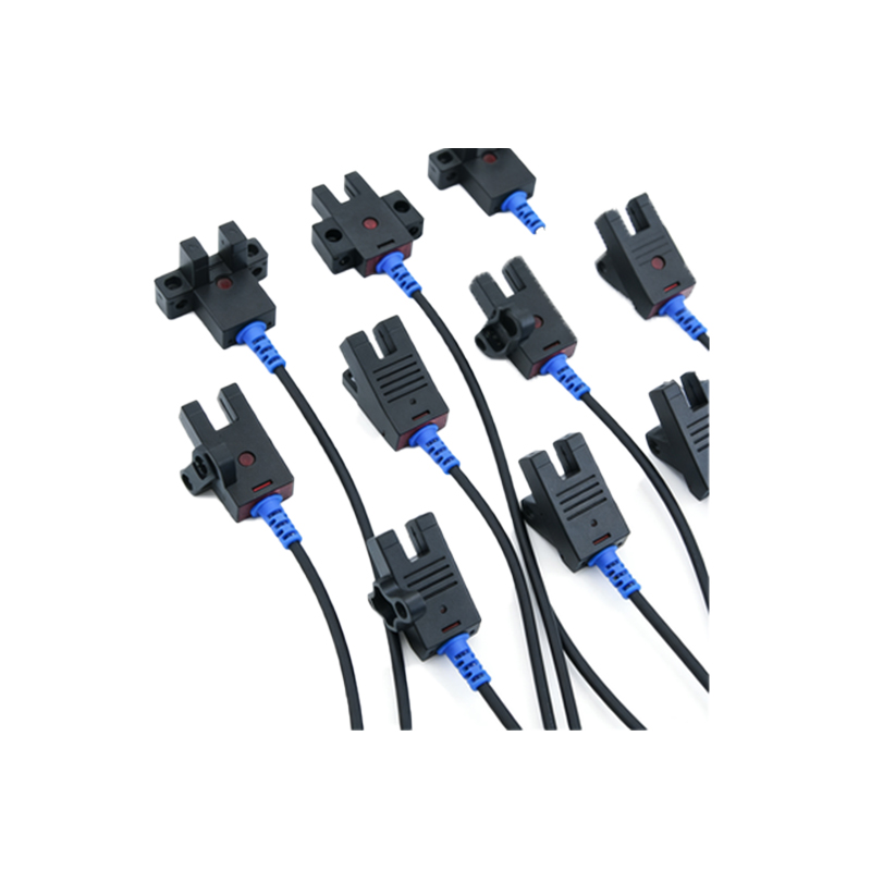
The physical interface is the first point of contact. Key terms include *Connector Type*, such as M8, M12, or rectangular housings, specifying the physical plug. *Pin Assignment* details the function of each conductor within the cable, commonly labeled: V+ or Brown wire for DC supply voltage, 0V or Blue wire for DC common, and OUT or Black wire for the switched output signal. *Cable Gland* refers to the strain relief entry point. *Wiring Diagram* is the schematic showing how to connect the sensor to a controller like a PLC. Phrases like "PNP Sourcing Output" (output switches positive voltage to load) and "NPN Sinking Output" (output switches ground to load) are crucial for correct circuit design.
Electrical Specification Parameters
The electrical interface defines operational limits. *Supply Voltage* is listed as a range, e.g., 10-30 VDC. *Current Consumption* indicates the sensor's own power draw. *Load Current* specifies the maximum current the output switch can handle, vital for connecting to PLC input modules or relays. *Voltage Drop* is the potential loss across the output switch when active. *Short-Circuit Protection* and *Reverse Polarity Protection* are critical safety features. *Switching Frequency* defines how fast the output can toggle, measured in Hertz (Hz). *Response Time* is the delay between sensing an object and changing the output state, typically in milliseconds.
Functional Modes and Operating Principles
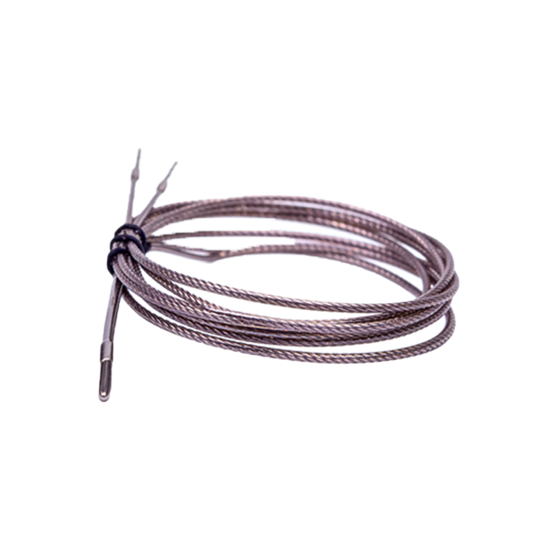
This describes the sensor's logic and detection method. *Light-On / Dark-On* operation defines the output state relative to light reception. *Operating Mode* includes *Through-Beam* (separate emitter and receiver), *Retroreflective* (with a reflector), and *Diffuse Reflective* (proximity mode). *Sensing Range* is the maximum reliable detection distance. *Adjustment* methods like *Sensitivity Potentiometer* or *Teach-In Button* are common. *Function Indicators* include a stable *Power LED* and a blinking or color-changing *Signal/Output LED* for status diagnostics. Terms like *Background Suppression* (BGS) and *Foreground Suppression* (FGS) describe advanced ranging techniques.
Output Configuration and Signal Types
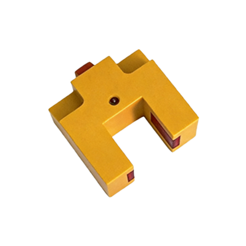
The output is how the sensor communicates its state. *Digital Output* is standard, with *NO* (Normally Open) and *NC* (Normally Closed) contacts. *Analog Output* provides a continuous signal, such as 0-10V or 4-20mA, proportional to distance or light intensity. *IO-Link* is a growing standard for smart sensor communication, enabling bidirectional data exchange for parameters, identification, and advanced diagnostics. *Push-Pull Output* is a specific circuit capable of both sourcing and sinking current. The term *Short-Circuit Proof* is often associated with the output stage's durability.
Communication Protocols and Smart Features
Modern sensors offer advanced digital interfaces. *IO-Link* is the dominant point-to-point protocol, detailed in its own section due to importance. *PROFINET*, *EtherNet/IP*, and *EtherCAT* are Ethernet-based protocols where sensors with integrated chips become network nodes. Terms like *Device Description File* (GSD, EDS) are needed for network configuration. *Data Matrix Code* on the sensor housing allows quick electronic identification and parameter assignment. *Diagnostic Messages* include "Short Circuit," "Supply Voltage Low," or "Lens Contamination" warnings transmitted via the communication channel.
IO-Link Specific Interface Terminology
As a key enabling technology, IO-Link has its own lexicon. The physical layer is standard 3-wire sensor cable (M12). *IO-Link Master* is the gateway device. *COM* refers to the communication mode (COM2/COM3 for speed). *Process Data* is cyclically exchanged primary information. *Service Data* includes device parameters, identification (Vendor ID, Device ID), and event information. *ISDU* (Index Service Data Unit) is the method for accessing parameter records. *Acyclic Communication* handles parameter read/write operations. *Event Reporting* allows the sensor to push diagnostic alerts.
Documentation and Labeling References
Finally, accurate translation applies to supporting materials. The *Datasheet* or *Technical Data* sheet contains all specifications. *Part Number* and *Ordering Code* are unique identifiers. *CE Marking*, *UL Listed*, or *IP Rating* (Ingress Protection, e.g., IP67) denote compliance and durability. *Mounting Bracket* and *Alignment Aid* are accessory terms. On the sensor body, labels like "V+", "OUT", "0V", "SET", and symbols for light/dark operation must be universally understood. Consistent use of these terms in manuals, drawings, and software is essential for seamless international engineering.