Understanding Reflective Photoelectric Sensors
Reflective photoelectric sensors are fundamental components in modern industrial automation, used for detecting the presence, absence, or distance of objects without physical contact. They operate by emitting a beam of light, typically infrared or visible LED, towards a reflective target. The sensor's receiver then detects the light reflected back. Key types include diffuse reflective sensors, which detect light bounced off the object itself, and retro-reflective sensors, which use a dedicated reflector. Understanding the basic operating principle is the first critical step before installation. Selecting the wrong type for the application is a primary cause of failure. For instance, a diffuse sensor might struggle with a dark, non-reflective object, while a retro-reflective sensor would be ideal for consistent detection of varied surfaces when paired with a proper reflector.
Critical Pre-Installation Considerations
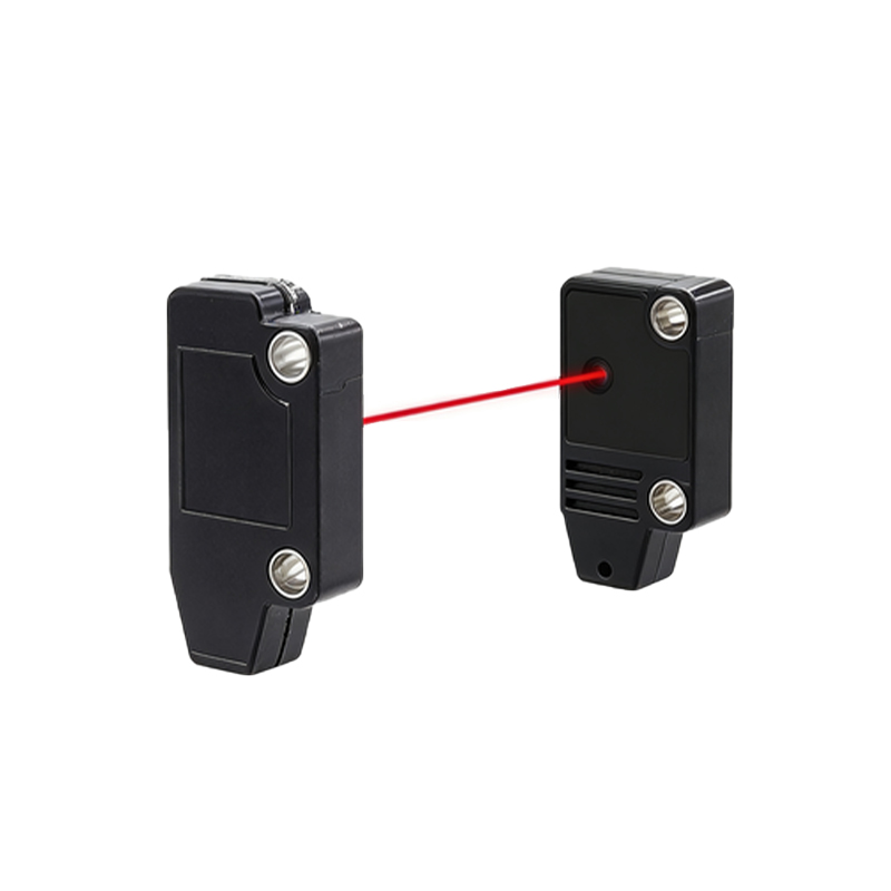
Thorough planning prevents poor performance. Begin by analyzing the application environment. Consider factors such as ambient light, which can include sunlight, strobe lights, or other sensor emissions that may cause interference. The presence of dust, fog, steam, or oil mist can scatter or absorb the light beam, reducing sensing reliability. The characteristics of the target object are equally vital: its color, material, surface finish (matte or glossy), size, and possible movement speed. A glossy target might create a mirror-like reflection, causing erratic detection. Furthermore, determine the required sensing distance and ensure the chosen sensor has an adequate operating range with a safety margin, typically 50-70% of its rated maximum to account for environmental degradation and component aging.
Optimal Mounting and Alignment Procedures
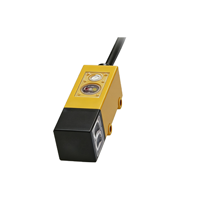
Precise mechanical mounting is non-negotiable. Always use the mounting brackets or hardware specified by the manufacturer to ensure stability and correct orientation. The sensor must be securely fastened to a vibration-free surface to prevent misalignment over time. For alignment, follow the manufacturer's guidelines. Many sensors feature a built-in alignment indicator, such as a green LED that lights when the beam is properly received. For retro-reflective sensors, ensure the reflector is mounted perpendicular to the sensor's beam axis. Even a slight angular deviation can drastically reduce the effective signal strength. Use a laser alignment tool if available for critical long-range applications. Avoid mounting sensors facing each other directly to prevent crosstalk.
Managing Environmental Light Interference
Ambient light is a pervasive challenge. To mitigate its effects, first, try to physically shield the sensor. Use mounting tubes, shrouds, or barriers to block direct sunlight or light from other sources. Many modern sensors incorporate modulated light technology, where the emitted light is pulsed at a specific high frequency. The receiver is tuned to this frequency, effectively filtering out constant or differently modulated ambient light. When installing in areas with intense or variable light, always opt for a modulated (AC) type sensor over a non-modulated (DC) type. Additionally, avoid placing sensors near highly reflective background surfaces, like stainless steel panels, which can cause false reflections and unintended triggering.
Electrical Wiring and Connection Best Practices
Correct electrical installation ensures sensor longevity and signal integrity. Strictly adhere to the wiring diagram provided in the sensor's datasheet, distinguishing between NPN (sinking) and PNP (sourcing) output types to match your controller's input. Use shielded cables in electrically noisy environments, such as those near variable frequency drives (VFDs) or large motors. Properly ground the shield at the control panel end only, creating a drain path for noise. Ensure wire gauges are appropriate for the current load and distance. Implement protective measures like surge suppressors if the sensor is connected to long cable runs or is in an area prone to lightning strikes. Always power the sensor within its specified voltage range and ensure a stable power supply to prevent erratic operation.
Fine-Tuning and Sensitivity Adjustment
After physical and electrical installation, fine-tuning is essential. Most reflective sensors feature a sensitivity potentiometer or teach-in function. The goal is to set the detection threshold reliably above the background noise but below the signal strength from a valid target. For a retro-reflective sensor, first adjust the sensitivity with the reflector in place until the output activates. Then, verify by breaking the beam; the output should deactivate. For diffuse sensors, use the actual target object. Place the target at the maximum required sensing distance and adjust the sensitivity until detection is consistent. Perform this adjustment under normal operating conditions, including typical ambient light and with the target moving at its standard speed, to account for real-world variables.
Routine Verification and Maintenance Protocols
Installation is not complete without establishing a maintenance schedule. Periodically inspect the sensor's lens for accumulation of dust, dirt, or condensation. Clean the lens gently with a soft, lint-free cloth and appropriate cleaner; never use abrasive materials. Check the tightness of mounting hardware and the integrity of cable connections. Re-verify the alignment and sensitivity settings at regular intervals, especially after any maintenance on surrounding machinery that might have disturbed the sensor. Log the sensor's performance baseline when first installed. This record allows for quick troubleshooting by comparing current signal strength or response times to the original values, helping to identify gradual degradation before a complete failure occurs.