Understanding Proximity Sensor Power Requirements
Proximity sensors, the workhorses of industrial automation, rely on a stable and correctly configured power supply for reliable operation. These non-contact devices, including inductive, capacitive, and ultrasonic types, typically operate on low-voltage DC power. Common voltage ratings are 10-30V DC, with 12V DC and 24V DC being the industry standards for most three-wire sensors. It is crucial to consult the sensor's datasheet to verify its specific voltage range, current consumption (often between 200mA), and whether it is sourcing (PNP) or sinking (NPN) type. Undervoltage can lead to erratic sensing or failure to trigger, while overvoltage can cause permanent damage to the internal circuitry. A regulated power supply with adequate current capacity and low ripple is essential to ensure consistent performance and longevity.
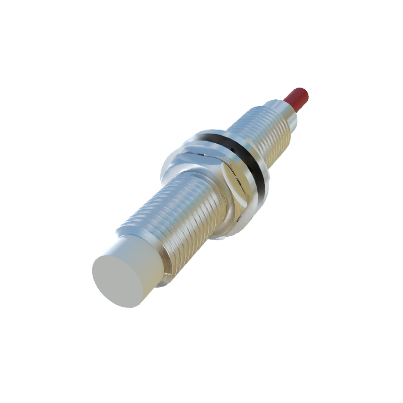
Core Wiring Principles and Connection Diagrams
Correct wiring is paramount for both functionality and safety. Three-wire sensors are most prevalent. For a DC sensor, the three wires are typically Brown (V+), Blue (V- or 0V), and Black (Output). The Brown wire connects to the positive terminal of the DC power supply, and the Blue wire connects to the negative terminal or common ground. The Black output wire connects to the load (e.g., a PLC input, relay, or indicator). For a PNP (sourcing) sensor, the output switches the positive voltage to the load. For an NPN (sinking) sensor, the output switches the ground connection to the load. Always ensure the load is compatible with the sensor's output type and current rating. Two-wire sensors, which connect in series with the load, simplify wiring but have limitations on leakage current and voltage drop.
Selecting the Appropriate Cable and Gland
The choice of cable and its entry point into the sensor housing significantly impacts system durability. Use shielded, multi-conductor cables designed for industrial control circuits. The cable shield, usually a braided or foil layer, must be properly grounded at the control panel end to drain electromagnetic interference (EMI) and prevent false triggering from nearby motors or frequency drives. The cable gauge must be sufficient to handle the sensor's current over the required distance without excessive voltage drop. For long runs, calculate the voltage drop and consider using a thicker gauge. At the sensor, a properly sized and rated cable gland ensures an IP67 or higher ingress protection rating, sealing out dust and moisture. Strain relief features within the gland prevent tension on the internal connections.
Grounding and Shielding for Noise Immunity
Industrial environments are electrically noisy. Proper grounding and shielding are non-negotiable for stable sensor operation. Always establish a single-point, low-impedance ground reference for the entire control system. Connect the shield of the sensor cable to this ground point at the control cabinet, typically via a shield clamp or terminal block. Do not connect the shield at both ends, as this can create ground loops which induce noise. Keep sensor cables separated from high-voltage power cables by at least 200mm. If crossing is unavoidable, do so at a 90-degree angle to minimize inductive coupling. Using twisted-pair wires for the DC supply and signal within the cable can further enhance noise rejection.
Power Supply Considerations and Protection
The power supply is the foundation. A dedicated, switch-mode or linear DC power supply for the sensor network is recommended, isolated from other high-power circuits. Incorporate protective devices in the power line. A fast-acting fuse or circuit breaker (rated just above the total sensor network current) protects against short circuits. A small-value ceramic capacitor (e.g., 100nF) placed close to the sensor's power terminals can help suppress high-frequency noise. For installations prone to voltage spikes or surges, such as those with large inductive loads, consider installing a transient voltage suppression (TVS) diode or a metal-oxide varistor (MOV) across the power lines at the distribution point.
Troubleshooting Common Power and Wiring Issues
When a proximity sensor fails, power and wiring are the first suspects. Use a digital multimeter to check for the presence of correct voltage between the Brown and Blue wires at the sensor connector. Verify that the voltage remains stable under load. Check for continuity and shorts in the cable. If the sensor output is erratic, investigate ground potential differences between the sensor and the load; a separate ground wire for the sensor body may be needed. Indicator LEDs on the sensor are invaluable for diagnostics—a steady power LED indicates good supply, while a flickering output LED may point to noise interference or a fluctuating target. Always follow lock-out/tag-out procedures before inspecting wiring