Understanding Banner Photoelectric Sensor Fundamentals
Banner photoelectric sensors are widely used in industrial automation for detecting the presence, absence, or position of objects. These sensors operate by emitting a beam of light (visible, infrared, or laser) and measuring the light that returns to a receiver. The three primary sensing modes are through-beam, retro-reflective, and diffuse (proximity). In through-beam mode, the emitter and receiver are separate units; an object is detected when it interrupts the light beam. Retro-reflective sensors use a reflector to bounce light back to the receiver, with detection occurring when the beam is blocked. Diffuse sensors rely on light reflecting directly off the target object. Understanding which mode your application uses is the first critical step in effective debugging, as each has unique alignment and environmental considerations.
Initial Setup and Power Connection
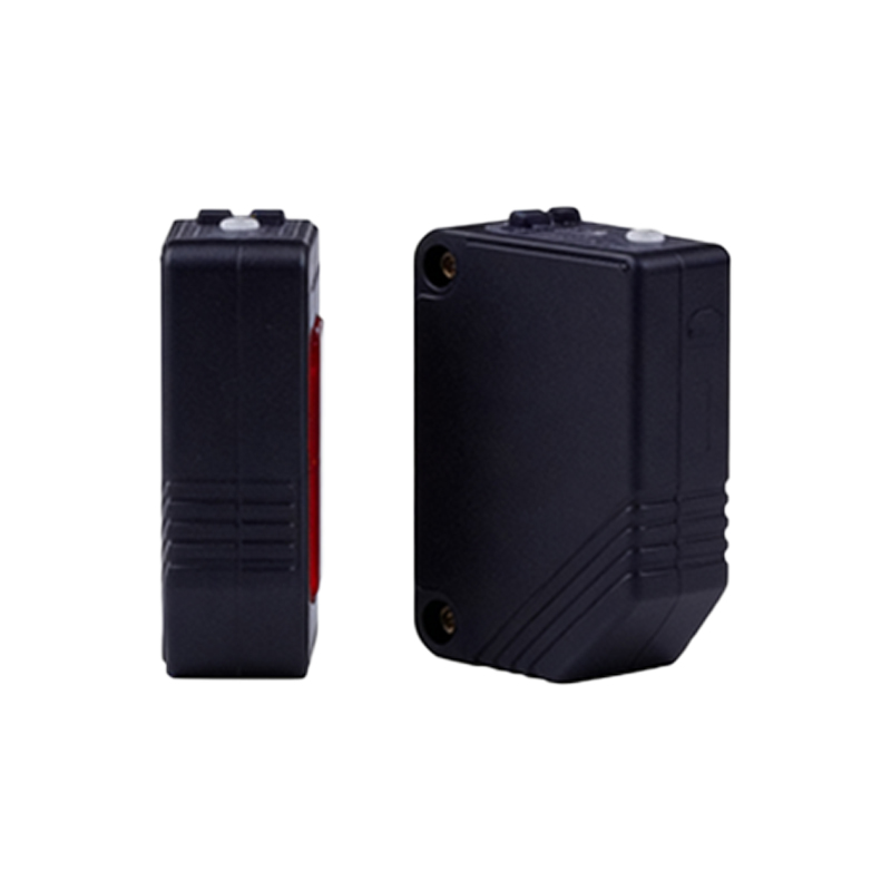
Before beginning the debug process, ensure the sensor is correctly installed and powered. Most Banner sensors operate on DC voltages (10-30 VDC) or AC voltages, as specified in the datasheet. Verify the power supply matches the sensor's requirements and that wiring is secure, following the wiring diagram (typically, brown wire to positive, blue wire to negative, and black wire as the output). Incorrect power can lead to erratic behavior or no response. After connecting power, check the sensor's indicator LED. A steady or blinking light usually indicates proper power and standby mode. If the LED is off, re-examine power connections, voltage levels, and potential fuse issues. Always follow lock-out/tag-out procedures when working with electrical systems to ensure safety.
Aligning the Sensor for Optimal Performance
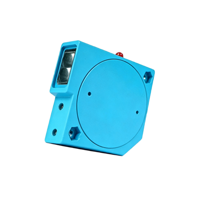
Misalignment is a common cause of sensor failure. For through-beam sensors, carefully align the emitter and receiver so that the light beam is centered. Use the sensor's alignment indicators or an alignment tool if provided. For retro-reflective sensors, ensure the reflector is clean and squarely aligned with the sensor; even slight angular deviations can reduce signal strength. Diffuse sensors require precise positioning relative to the target's surface, distance, and color, as reflectivity affects performance. Banner sensors often feature a "teach" or "set" button for configuring sensitivity thresholds. Press this button while the target is present to set the detection level. After alignment, test by passing an object through the sensing field and observing the output LED and control system response.
Adjusting Sensitivity and Response Time
If alignment is correct but detection is inconsistent, adjust the sensitivity potentiometer on the sensor. Turn it clockwise to increase sensitivity (for low-reflectivity targets or longer ranges) or counterclockwise to decrease it (to avoid false triggers from background objects). Banner sensors may also have response time settings to filter out noise or rapid fluctuations; a slower response can stabilize output in vibrating environments. Use a multimeter to monitor the output signal or connect to a PLC for verification. For advanced models with digital displays, consult the manual to navigate menu settings for fine-tuning. Keep in mind that environmental factors like dust, moisture, or ambient light can impact sensitivity, so adjustments may need periodic revisiting.
Troubleshooting Common Issues
When a Banner sensor fails to operate as expected, systematic troubleshooting is key. Start by checking the output LED: if it toggles when an object is detected but the PLC doesn't register it, the issue may lie in wiring or the load. Verify output wiring and ensure the load (e.g., relay, PLC input) is within the sensor's rated capacity. If the LED doesn't change, re-evaluate alignment and sensitivity. For intermittent operation, inspect for loose connections, power fluctuations, or environmental interference such as strong ambient light (use a shielded sensor or sunshade) or cross-talk from nearby sensors (stagger mounting distances or frequencies). Cleaning the lens and reflector with a soft cloth can resolve problems caused by dirt or debris accumulation.
Utilizing Diagnostic Features and Tools
Many Banner photoelectric sensors include built-in diagnostics to aid debugging. Features like stability indicators (showing signal strength) or dual LEDs (for power and output status) provide real-time feedback. For precise measurements, use Banner's proprietary tools or a photoelectric sensor tester to measure received light intensity, helping identify weak signals. Additionally, some models offer IO-Link communication for digital parameter adjustment and monitoring via software. If problems persist, refer to the sensor's manual for error codes or performance curves. Documenting settings and environmental conditions during debugging can expedite future maintenance and ensure reliable long-term operation in conveyor, packaging, or assembly applications.