Understanding 2-Wire Photoelectric Sensor Basics
A 2-wire photoelectric sensor is a fundamental component in industrial automation, designed for simplicity and space efficiency. Unlike its 3-wire or 4-wire counterparts, it integrates both power supply and switching signal into a single pair of wires. This design allows it to function similarly to a mechanical switch, making it easy to retrofit into existing control systems. The sensor operates by emitting a light beam—typically infrared, visible red, or laser—and detecting changes in the received light intensity caused by an object's presence or absence. Its two wires connect directly in series with the load, such as a relay coil, programmable logic controller (PLC) input, or indicator lamp. The key advantage lies in its straightforward wiring, but it requires careful consideration of electrical parameters like voltage drop and load compatibility to ensure reliable operation.
Essential Pre-Installation Considerations
Before connecting the sensor, verify the electrical specifications of both the sensor and the control system. Check the sensor's datasheet for its operating voltage range (commonly 10-30V DC or 20-250V AC), maximum load current, and leakage current. For DC sensors, polarity is crucial; the brown wire (or labeled +) typically connects to the positive supply, while the blue wire (or labeled -) links to the load and then to the negative side. In AC models, polarity is not a concern, but ensure the voltage type matches. Calculate the total load impedance to confirm it falls within the sensor's rated capacity. Insufficient load may prevent the sensor from turning off completely due to residual leakage current, causing phantom signals. Also, assess environmental factors like ambient light interference, dust, or moisture, which might necessitate selecting a sensor with appropriate housing (e.g., IP67 rating) or sensing mode (through-beam, retro-reflective, or diffuse).
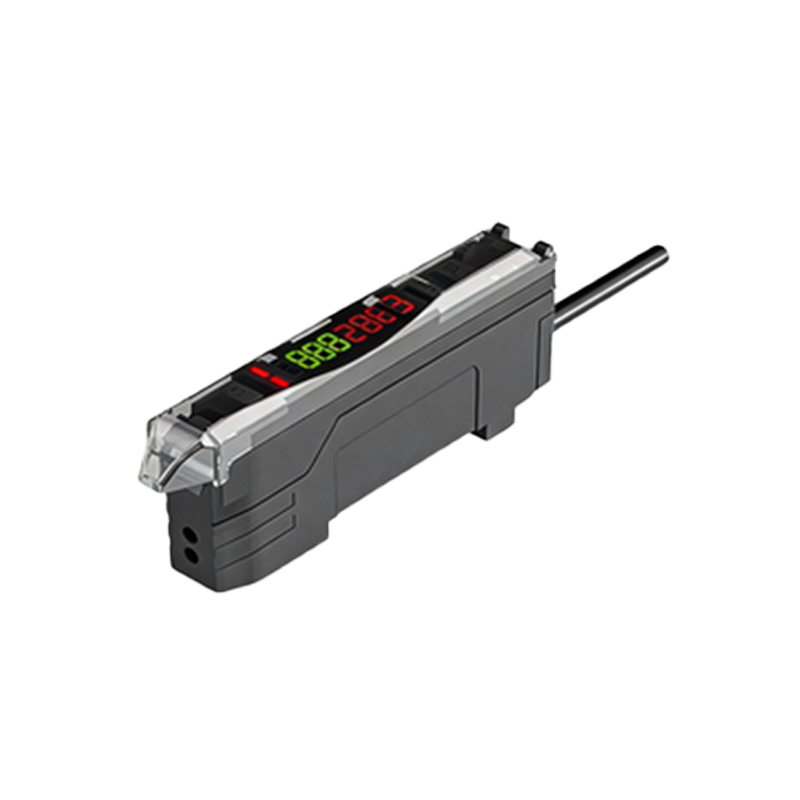
Step-by-Step Wiring Procedure for DC Circuits
For a typical 24V DC application, start by de-energizing the control circuit to prevent short circuits or damage. Identify the power source—often a 24V DC supply—and the load, such as a PLC digital input module. Connect the brown wire from the sensor to the positive terminal of the power supply. Then, link the blue wire from the sensor to one terminal of the load. Finally, wire the other terminal of the load back to the negative side of the power supply, completing the series circuit. Use shielded cables in electrically noisy environments, grounding the shield at one end to minimize interference. After connections, apply power and test the sensor by introducing a target object within its sensing range. Observe the load response; for instance, a PLC input LED should illuminate upon detection. If the sensor fails to trigger, double-check wiring polarity, measure voltage across the load to ensure it meets the minimum threshold, and verify the sensing alignment.
Wiring in AC Systems and Load Compatibility
In AC systems (e.g., 120V AC), the process is similar but with attention to safety standards. Use the brown wire for the live (hot) conductor and the blue wire for the load connection. Since AC sensors are often used with higher voltages, employ proper insulation and enclosures to meet regulatory codes. The load in AC circuits might be a contactor coil or an AC input module. Remember that 2-wire sensors have an inherent voltage drop—usually 2-5 volts—which reduces the voltage available to the load. This drop is critical in low-voltage applications; for example, a 24V DC system with a 3V drop might not provide enough voltage for some PLC inputs. Always consult the load's specifications to ensure the residual voltage exceeds its "ON" state requirement. Additionally, consider inrush currents from inductive loads like solenoids, which can exceed the sensor's switching capacity and cause premature failure. A protective snubber circuit or relay may be necessary for such cases.
Troubleshooting Common Connection Issues
If the sensor malfunctions, systematic troubleshooting can identify the root cause. First, measure the voltage across the sensor terminals with a multimeter; it should be near the supply voltage when the sensor is off and drop significantly when on. High leakage current (typically 1-2 mA) might keep the load partially energized; adding a bypass resistor in parallel with the load can dissipate this current. For false triggers, check for environmental interference like reflective surfaces or strong ambient light, and adjust the sensor's sensitivity or mounting angle. In noisy industrial settings, electromagnetic interference (EMI) can affect performance; ensure proper grounding and use twisted-pair cables. If the sensor overheats or fails, verify that the load current does not exceed the sensor's maximum rating. For persistent issues, refer to the manufacturer's guidelines—some sensors feature diagnostics via LED indicators, showing power status or output activation. Regular maintenance, including lens cleaning and connection checks, prolongs sensor life and reliability.
Best Practices for Optimal Performance
To maximize efficiency, follow industry best practices. Select a sensor with a sensing range 20-30% larger than the actual application requirement to account for alignment tolerances. Use conduit or cable glands in harsh environments to protect wiring from physical damage. Label all wires clearly for future maintenance. When integrating with PLCs, ensure the input module is compatible with 2-wire sensors—some PLCs require 3-wire connections due to input impedance characteristics. For long cable runs, consider voltage drop along the wires; thicker gauge cables can mitigate this. Document the wiring diagram and keep it accessible for troubleshooting. Finally, stay updated with sensor technology advancements; newer models offer features like IO-Link connectivity for smart diagnostics, which can simplify wiring and enhance system monitoring. By adhering to these principles, engineers can ensure robust and reliable sensor integration in diverse automation projects.