Understanding Proximity Switch Sensor Terminals
Proximity switch sensors are essential components in industrial automation, detecting the presence or absence of objects without physical contact. Their terminals serve as the critical interface for electrical connections, typically including power supply, output, and ground points. Common terminal types include screw terminals, spring-cage terminals, and plug-in connectors, each designed for specific installation environments and wire gauges. Proper identification of these terminals—often labeled as V+ (power positive), V- (power negative/ground), and OUT (output signal)—is fundamental to ensuring correct functionality. Misidentification can lead to sensor failure or system malfunctions, emphasizing the need for careful reference to the manufacturer's datasheet before any wiring procedure.
Step-by-Step Wiring Procedure
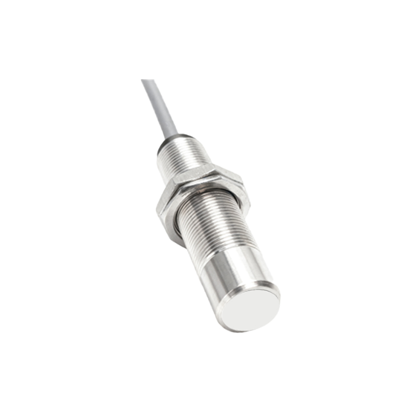
Begin by disconnecting all power sources to prevent electrical hazards. Strip the insulation from the wires to expose an appropriate length of conductor, usually 7-10 mm, ensuring no stray strands remain. For screw terminals, insert the wire into the terminal block and tighten the screw firmly to secure the connection, avoiding over-tightening which may damage the wire. With spring-cage terminals, use a dedicated release tool to open the cage, insert the wire, and release to clamp it securely. Connect the power wires first: attach the positive wire (e.g., brown) to V+ and the negative wire (e.g., blue) to V-. Next, link the output wire (e.g., black) to the OUT terminal for signal transmission. Always verify that wire colors align with local electrical standards or the sensor's documentation to maintain consistency and safety.
Common Wiring Configurations
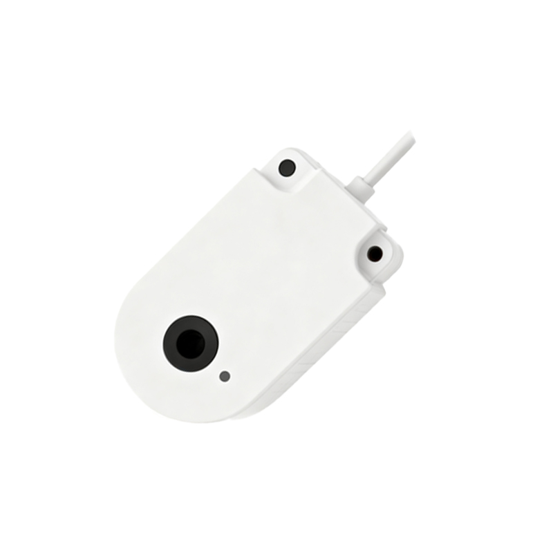
Proximity sensors generally operate in two primary configurations: NPN (sinking) and PNP (sourcing). In NPN setups, the output terminal connects to the load, which is then linked to positive voltage, causing the sensor to "sink" current to ground when activated—common in Asian and European markets. Conversely, PNP configurations have the output providing positive voltage to the load, "sourcing" current, and are prevalent in North America. Additionally, 2-wire, 3-wire, and 4-wire models exist: 2-wire sensors simplify installation by combining power and output but may have higher leakage current; 3-wire versions offer separate power and output lines for enhanced reliability; 4-wire sensors include dual outputs (e.g., normally open and normally closed) for flexible control. Selecting the right configuration depends on the control system's compatibility and operational requirements.
Troubleshooting Connection Issues
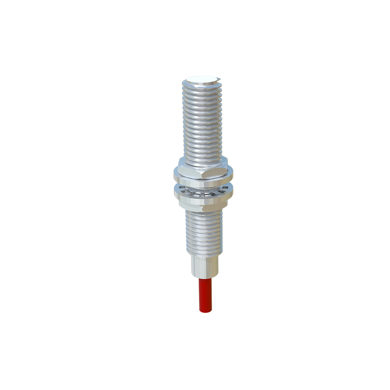
If a proximity sensor fails to operate post-installation, start by checking terminal connections for loose wires or poor contact—re-secure any problematic terminals. Use a multimeter to measure voltage at the power terminals, ensuring it matches the sensor's rated supply (e.g., 10-30 V DC). For output issues, test the signal wire: in active state, the output should switch between 0 V (off) and the supply voltage (on), depending on the configuration. Inspect for short circuits or crossed wires, especially between power and output terminals, which can cause permanent damage. Environmental factors like moisture or metal shavings near terminals may also lead to intermittent faults; consider using sealed connectors or protective covers in harsh conditions. Consult the sensor's indicator LED, if available, for status clues such as power-on or detection signals.
Best Practices for Terminal Maintenance
Regular maintenance prolongs sensor life and ensures reliable performance. Periodically inspect terminals for corrosion, oxidation, or physical damage, cleaning them with a soft brush or contact cleaner if needed. Ensure terminal screws remain tight, as vibration in industrial settings can loosen connections over time. For plug-in connectors, check for bent pins or wear, and replace them promptly to avoid signal loss. Implement proper strain relief by securing cables near the terminal block, preventing tension on the wires that could break connections. Label all wires and terminals clearly to simplify future repairs or modifications. Finally, adhere to the sensor's environmental ratings—avoid exposing terminals to extreme temperatures, chemicals, or excessive dust without adequate protection, as these can degrade electrical integrity.