Introduction to 4-Wire Proximity Switch Sensors
In industrial automation, proximity sensors are indispensable for detecting the presence or absence of objects without physical contact. Among various configurations, the 4-wire proximity switch sensor stands out due to its dual functionality. Unlike 2-wire or 3-wire variants, a 4-wire sensor typically incorporates two separate circuits: one for power supply and another for the output signal. This design allows for independent switching of both normally open (NO) and normally closed (NC) contacts, providing greater flexibility in control logic. The connector, a critical interface component, ensures reliable electrical connections between the sensor and the control system, such as a PLC (Programmable Logic Controller). Understanding the wiring, pin configurations, and selection criteria for these connectors is essential for engineers and technicians to optimize system performance and minimize downtime.
Wiring Configuration and Pin Assignments
The standard wiring for a 4-wire proximity sensor connector follows a consistent color-coding and pinout scheme, though variations may exist by manufacturer. Typically, the four wires are designated as: brown for positive DC supply voltage (e.g., +24V), blue for negative or common ground (0V), black for the normally open (NO) output, and white for the normally closed (NC) output. The connector housing, often made of durable plastics like PBT or nylon, includes pins that match these wires. For instance, in a common M12 circular connector, pin 1 is usually for brown (power+), pin 2 for black (NO), pin 3 for blue (power-), and pin 4 for white (NC). This arrangement enables simultaneous monitoring of both NO and NC states, allowing for fail-safe detection in safety-critical applications. Proper termination using crimping tools and secure locking mechanisms, such as threaded couplings or push-pull designs, is vital to prevent disconnection in high-vibration environments.
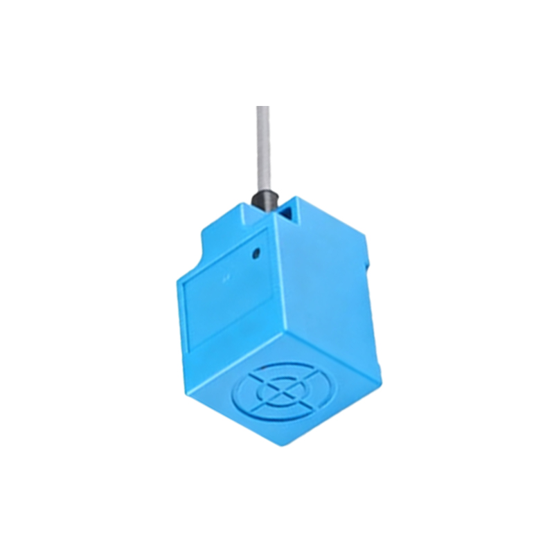
Key Features and Technical Specifications
4-wire proximity sensor connectors are engineered to meet rigorous industrial standards, including IP67 or IP69K ratings for dust and water resistance, ensuring reliability in harsh conditions like manufacturing floors or outdoor installations. They support a wide voltage range, commonly 10-30V DC, and offer switching currents up to 200mA, suitable for driving relays or PLC inputs. The sensors themselves can be inductive, capacitive, or photoelectric, with sensing distances varying from a few millimeters to several centimeters. Connectors often feature gold-plated contacts to reduce resistance and prevent corrosion, enhancing signal integrity over long cable runs. Additionally, shielding options are available to minimize electromagnetic interference (EMI) from nearby motors or frequency drives, which is crucial for maintaining accurate detection in noisy electrical environments.
Selection Criteria for Industrial Use
Choosing the right 4-wire proximity switch connector involves evaluating several factors. First, consider the environmental conditions: for high-temperature areas, connectors with thermoplastic housings that withstand up to 125°C are preferred. Next, assess the mechanical stress; in applications with constant movement, such as robotic arms, connectors with strain relief and robust locking are essential. Compatibility with existing systems is also key—ensure the connector type (e.g., M8, M12, or 7/8-inch) matches the sensor and control panel interfaces. Cost-effectiveness should balance initial price with lifecycle durability; opting for certified products from reputable brands can reduce maintenance costs. Finally, verify compliance with industry standards like IEC 60947-5-2 for proximity devices, which guarantees safety and performance consistency across installations.
Installation and Maintenance Best Practices
Proper installation of 4-wire proximity sensor connectors starts with de-energizing the system to prevent electrical hazards. Strip the cable insulation to the recommended length, crimp the wires securely to the connector pins, and insert them into the housing according to the pinout diagram. Use a torque wrench for threaded connectors to avoid over-tightening, which can damage seals. After connection, perform functional tests by simulating object detection to verify both NO and NC outputs switch correctly. For maintenance, regularly inspect connectors for signs of wear, corrosion, or loose fittings, especially in high-vibration settings. Cleaning with isopropyl alcohol can remove contaminants without degrading materials. Implementing preventive schedules, such as annual checks, helps extend connector lifespan and ensure uninterrupted operation in automated processes.
Common Applications and Benefits
4-wire proximity switch sensors with dedicated connectors are widely used in industries like automotive assembly, packaging, and material handling. In conveyor systems, they detect product positions to trigger sorting mechanisms via both NO and NC signals, enabling redundant monitoring for error prevention. In