Introduction to Proximity Switch Sensor Assemblies
In the intricate ecosystem of modern elevator systems, the proximity switch sensor assembly stands as a critical, yet often understated, component. This assembly is fundamentally responsible for the precise detection of the elevator car's position within the hoistway and the status of its doors. Unlike mechanical limit switches, proximity sensors operate without physical contact, using electromagnetic fields to detect the presence of a metallic target. This non-contact principle ensures higher reliability, longer operational life, and minimal maintenance, making them indispensable for the smooth and safe operation of both passenger and freight elevators. The assembly typically integrates multiple sensors, mounting hardware, and necessary wiring into a cohesive unit designed for specific installation points.
Core Operating Principles and Technologies
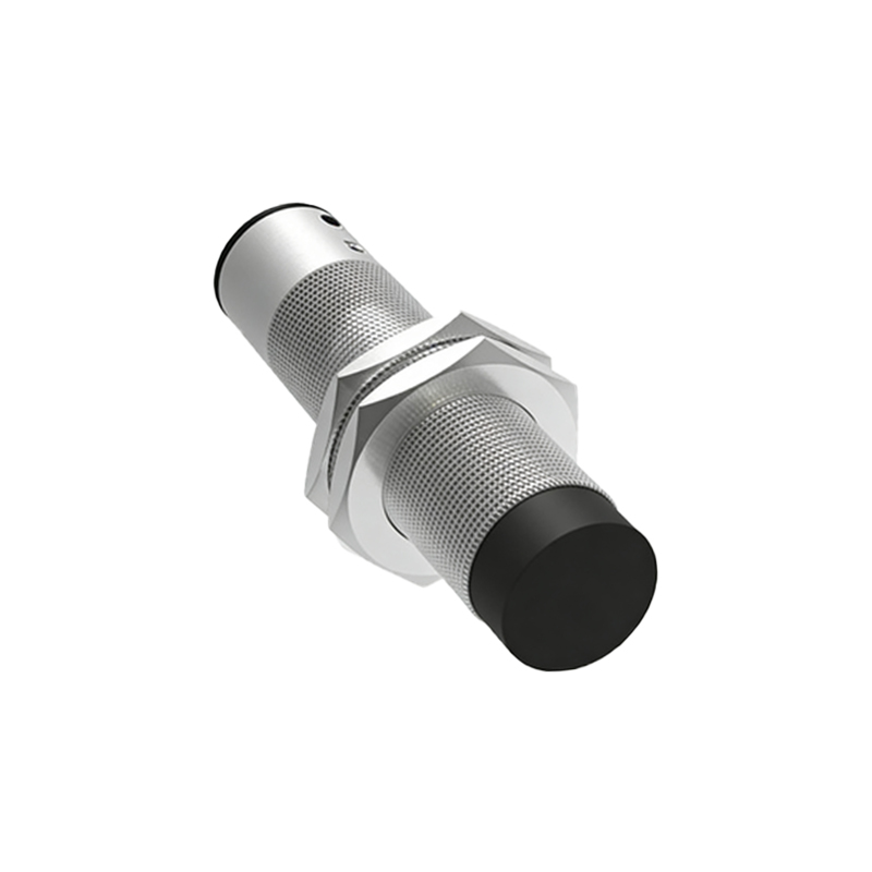
The functionality of an elevator proximity sensor assembly hinges on two primary technologies: inductive and magnetic (reed or Hall effect) sensing. Inductive proximity sensors are the most common. They generate an oscillating electromagnetic field. When a metal target—such as a vane or tab mounted on the moving elevator car—enters this field, it induces eddy currents within the target. This causes a change in the sensor's oscillation amplitude, which is detected by the internal circuitry, triggering a solid-state output signal. Magnetic sensors, on the other hand, react to the presence of a permanent magnet. These are frequently used for door zone detection and safety edge applications. The choice between technologies depends on factors like required sensing distance, target material, environmental conditions, and cost considerations.
Key Components and Assembly Configuration
A complete proximity switch sensor assembly is more than just the sensors themselves. It is a systematically engineered package. The primary components include the sensor heads, often housed in rugged, oil-resistant polymer or metal casings rated for IP67 or higher to withstand the harsh hoistway environment. These are mounted on a rigid bracket or rail, precisely aligned for optimal detection. The assembly includes pre-terminated wiring harnesses or junction boxes for simplified connection to the elevator's main controller. Critical alignment tools or gauges are sometimes part of the kit to ensure installation accuracy. The assembly is designed for specific locations: top and bottom final limit positions, door zone registration, leveling, and re-leveling points throughout the hoistway.
Critical Role in Elevator Safety and Performance
The sensor assembly's role is paramount for both safety and ride quality. Safety functions are non-negotiable. Sensors defining the upper and lower terminal stopping limits are the last line of defense to prevent the car from over-traveling. Door zone sensors ensure the car is correctly positioned before doors can open, preventing hazardous gaps. For performance, the assembly enables precise floor leveling. As the car approaches a floor, sensors detect reference vanes, allowing the control system to micro-adjust the motor to bring the car floor flush with the landing floor. This precision directly impacts passenger comfort and accessibility. Furthermore, sensors monitor door operation, ensuring they are fully closed and locked before travel commences.
Installation, Alignment, and Calibration Procedures
Proper installation is critical for reliable operation. The mounting bracket must be securely fixed to the hoistway wall or guide rail with minimal vibration. The sensor heads require precise gap alignment relative to their target vanes or magnets; this gap is typically specified within a tight tolerance (e.g., 2mm ±0.5mm). Using a non-magnetic feeler gauge is standard practice. Alignment must account for the full travel path, ensuring the target passes through the sensor's active zone without collision. After physical installation, electrical calibration is performed. This often involves verifying the output signal (PNP/NPN, NO/NC) with the controller and setting any adjustable parameters like response time or hysteresis to prevent signal chatter due to vibration.
Common Failure Modes and Diagnostic Techniques
Despite their robustness, sensor assemblies can fail. Common issues include physical damage from impact, accumulation of metallic dust or debris on the sensing face, moisture ingress compromising electronics, and wiring faults such as broken conductors or poor connections. Electrical interference from motor drives or power cables can also cause erratic signals. Diagnostics begin with a visual inspection for obvious damage or misalignment. A multimeter is used to check power supply voltage at the sensor and to monitor the output signal state while manually moving the target. Oscilloscopes can reveal signal noise. Modern elevator controllers often provide diagnostic logs that record fault codes related to sensor time-outs or signal inconsistencies, greatly aiding troubleshooting.
Maintenance Best Practices and Industry Trends
Preventive maintenance is straightforward but essential. Scheduled inspections should verify the physical integrity of the assembly, cleanliness of sensor faces, tightness of mounting hardware, and security of