Understanding Slot Type Photoelectric Sensors
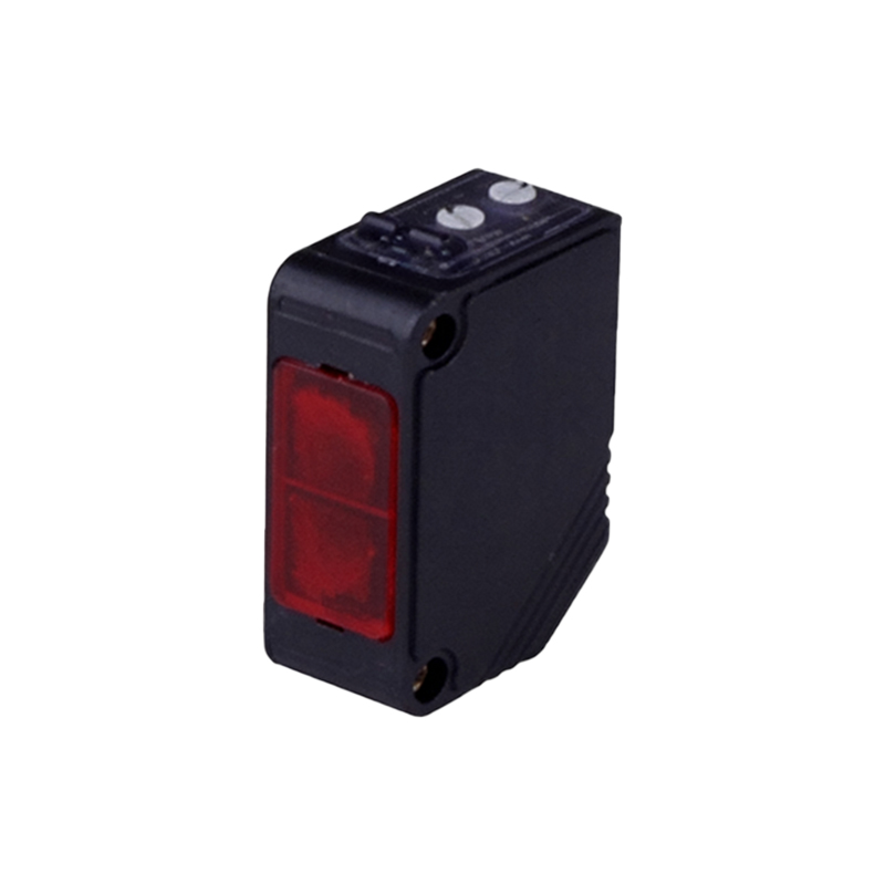
A slot type photoelectric sensor, often called a through-beam sensor, consists of two separate components housed in a single U-shaped body: an emitter on one side and a receiver on the other. The emitter continuously projects a beam of light, typically infrared or visible red, across the open slot to the receiver. When an object passes through this slot, it interrupts the light beam. This interruption is detected by the receiver, which then changes its output state. These sensors are known for their high precision and reliability in detecting even very small objects, making them ideal for applications like counting, positioning, and, as discussed here, automated on/off control. Their self-contained design simplifies alignment compared to separate emitter-receiver pairs, as the optical path is fixed at the factory.
Key Components and Electrical Specifications
Before wiring, it is crucial to understand the sensor's specifications. Common output types for DC-powered slot sensors include NPN (sinking) and PNP (sourcing) transistor outputs. For controlling an AC light bulb, a relay is almost always necessary as an intermediary, as the sensor's solid-state output cannot directly handle the high voltage and alternating current of a typical light circuit. The sensor itself requires a DC power supply, often 12-24V DC. You must consult the sensor's datasheet to identify the wiring terminals: typically, brown wire for DC+, blue wire for DC-, and black wire for the output signal. The load (in this case, the relay coil) will be connected between the black wire and either positive or negative, depending on whether it is an NPN or PNP configuration.
Circuit Design and Relay Integration
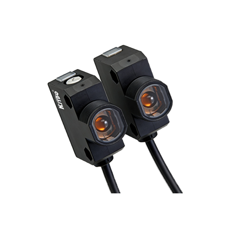
The core of this control system is the relay. It acts as a heavy-duty switch operated by the low-power signal from the photoelectric sensor. Design the circuit so that the sensor's output wire drives the coil of the relay. For an NPN sensor, the relay coil is connected between the sensor's black output wire and the positive supply voltage (+V). When the beam is unbroken, the NPN transistor is off, and no current flows to the relay coil. When an object interrupts the beam, the transistor turns on, completing the circuit to ground, energizing the relay coil, and closing its contacts. A PNP sensor would be wired with the coil between the output and ground. A protection diode (like a 1N4007) must be installed in reverse bias across the relay coil to suppress voltage spikes when the coil de-energizes.
Wiring the Mains Power for the Light Bulb
This part of the circuit involves standard AC mains wiring and must be performed with extreme caution, following all local electrical codes, ideally by a qualified electrician. The AC power source (e.g., 120VAC or 240VAC) is connected to one terminal of the light bulb's socket. The other socket terminal is connected to one of the relay's switch contacts (usually the Common or COM terminal). The remaining AC wire from the power source is connected to the relay's Normally Open (NO) contact. When the sensor is activated, the relay coil energizes, the NO contact closes, completing the AC circuit and illuminating the bulb. The entire AC circuit should be protected by a correctly rated fuse or circuit breaker. Ensure all AC connections are secure and properly insulated.
Step-by-Step Wiring Procedure
First, disconnect all power sources. Begin by wiring the low-voltage DC side. Connect the DC power supply's positive terminal to the sensor's brown wire and the negative terminal to the sensor's blue wire. Next, connect one side of the relay coil to the sensor's black output wire. Connect the other side of the relay coil to either the positive DC rail (for NPN) or the negative DC rail (for PNP), as per your design. Remember to solder the protection diode across the coil terminals. Now, for the high-voltage side, wire the AC hot wire to one terminal of the light bulb socket. Run a wire from the other socket terminal to the COM terminal of the relay's switch. Finally, connect the AC neutral wire to the relay's NO terminal. Double-check all connections against your circuit diagram.
Testing and Troubleshooting
After a thorough visual inspection, apply DC power only. Use a multimeter to verify the sensor receives the correct voltage. Pass an object through the sensor slot; you should hear a distinct click from the relay as it activates. If the relay does not click, check the DC polarity, sensor output type, and relay coil connections. Once the low-voltage side functions, disconnect power again before finalizing AC connections. After completing AC wiring, restore all power. The light bulb should now turn on only when an object interrupts the sensor's beam. If the bulb does not light, check the AC fuse, ensure the bulb is functional, and verify that the relay's switch contacts are properly wired to the NO circuit. For persistent issues, consult the sensor and relay datasheets for diagnostic indicators.
Common Applications and Safety Notes
This setup is widely used in automated systems. Examples include a light turning on in a dark cabinet when the door is opened (sensor on the frame, actuator on the door), a conveyor belt system where a package interrupts a beam to trigger a work light, or in safety curtains to indicate access. Always prioritize safety. The low-voltage control circuit should be physically separated and insulated from the high-voltage AC circuit. Use appropriate wire gauges—thin gauge for DC, thicker gauge for AC based on current draw. Enclose all AC wiring in a proper electrical enclosure to prevent accidental contact. Regularly inspect the system for wear and ensure the sensor lens remains clean for reliable operation.