Understanding Photoelectric Sensor Wiring Fundamentals
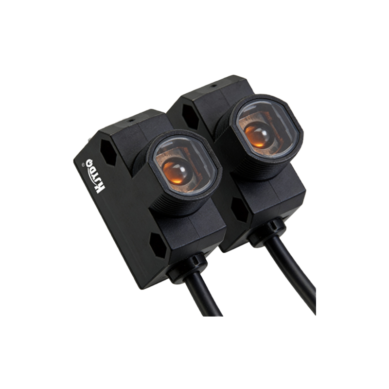
Photoelectric sensors are ubiquitous in industrial automation, serving critical roles in object detection, positioning, and counting. Their operation hinges on emitting a light beam (infrared, visible red, or laser) and detecting changes in the received light. A standard three-wire DC sensor typically features a brown wire for positive voltage supply, a blue wire for the common negative or 0V, and a black wire for the output signal. The black wire is the primary focus for connecting the sensor's detection state to a controller like a PLC, relay, or counter. Misunderstanding its function is a common source of installation errors and system malfunctions. Proper wiring is not merely about making electrical connections; it ensures reliable signal transmission, protects sensitive control equipment, and guarantees the longevity of the sensor itself. Before handling any connections, always consult the specific sensor's datasheet, as wire colors and functions can vary between manufacturers and sensor types (e.g., NPN vs. PNP output).
Decoding NPN and PNP Output Configurations
The wiring procedure for the black output wire is entirely dependent on whether the sensor has an NPN or PNP transistor output. This distinction defines the switching logic and current flow. A PNP sensor, often described as "sourcing" output, switches the positive voltage. In its active state (detection), the black wire connects the internal circuit to the positive supply, sourcing current to the load. The load (e.g., a PLC input) is connected between the black wire and the negative supply (blue wire). Conversely, an NPN sensor, or "sinking" output, switches the negative path. When active, the black wire connects the load to the negative supply, sinking current from it. Here, the load is connected between the positive supply (brown wire) and the black wire. Confusing these two types is the most frequent wiring mistake. A simple mnemonic: PNP = Positive Switched, NPN = Negative Switched. Always verify the sensor's model number and markings to confirm its output type before proceeding.
Step-by-Step Wiring Procedure for the Black Wire
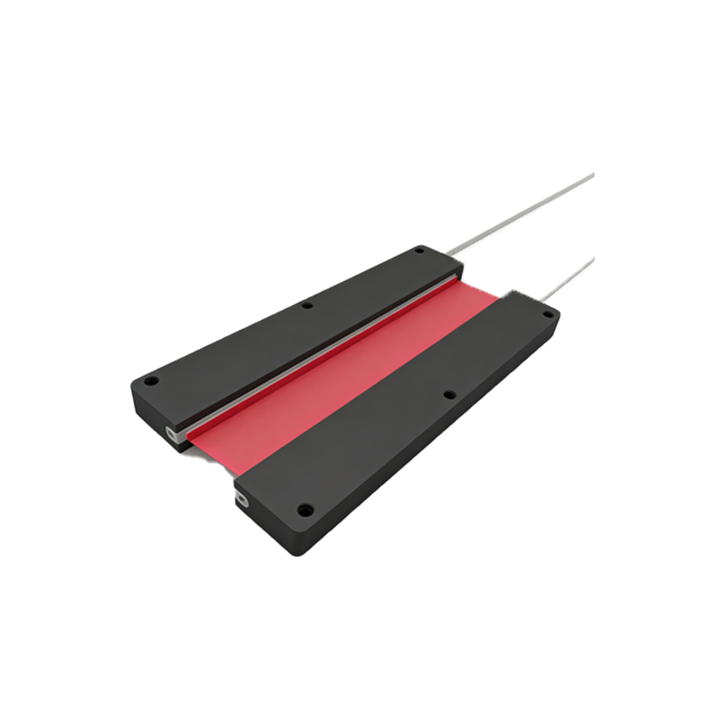
For a standard 3-wire DC sensor, follow this systematic approach. First, ensure the power is completely disconnected. Identify the wires: brown (+V), blue (0V/Common), and black (Output). Connect the brown wire to the positive terminal of your DC power supply (typically +12V or +24V). Connect the blue wire to the negative terminal of the same supply. Now, for the critical black wire connection, you must connect it to your load device. The other side of the load must be connected to complete the circuit, which differs for NPN and PNP. For a PNP sensor: Connect the black wire to one terminal of your load (e.g., PLC input channel X0). Connect the other terminal of that load to the negative supply (blue wire or 0V). For an NPN sensor: Connect the black wire to one terminal of your load. Connect the other terminal of that load to the positive supply (brown wire or +V). Finally, securely tighten all connections and use appropriate ferrules or terminal lugs to prevent strand breakage.
Connecting to Programmable Logic Controllers (PLCs)
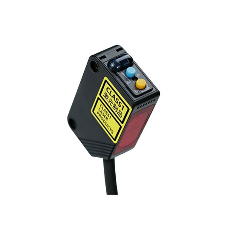
Integrating a photoelectric sensor with a PLC is a common application. PLC input cards are typically designed to work with either sinking (NPN) or sourcing (PNP) signals, though many modern cards are universal. You must match the sensor's output type to the PLC input's expected configuration. For a PNP sensor connecting to a sinking PLC input: The PLC input card provides the path to 0V. The black wire from the sensor connects directly to the PLC input terminal. The sensor's blue wire and the PLC input's common (COM) are both connected to 0V. For an NPN sensor connecting to a sourcing PLC input: The PLC input card provides the +V source. The black wire from the sensor connects to the PLC input terminal. The sensor's brown wire and the PLC input's common (COM) are both connected to +V. Incorrect pairing, such as an NPN sensor with a sinking input, will result in no signal change. Always reference both the sensor and PLC hardware manuals.
Common Troubleshooting and Safety Practices
If the sensor does not operate after wiring, methodically check these points. First, verify power: Use a multimeter to confirm +V between brown and blue wires. Second, check the output state: Many sensors have a built-in LED indicator that lights when the output is active. Trigger the sensor and observe. Third, measure the black wire voltage relative to blue (0V). For a PNP sensor, it should swing from near 0V (inactive) to near +V (active). For an NPN, it should swing from near +V (inactive) to near 0V (active). Fourth, inspect for short circuits or incorrect load connections. A critical safety practice is to always use a separate, fused power supply for sensors and control circuits, isolating them from motor power lines to prevent electrical noise interference. Ensure all connections are in enclosed cabinets for protection. Never disconnect wires under power, and always follow lock-out/tag-out (LOTO) procedures during installation or maintenance.