Introduction to Proximity Sensor Identification
In the realm of industrial automation and electrical engineering, proximity sensors are indispensable components for non-contact detection. Their representation in schematic diagrams, ladder logic, and equipment nameplates follows standardized conventions. Understanding these symbols and letter codes is crucial for design, installation, troubleshooting, and maintenance. This alphanumeric language, often derived from international standards like IEC 61346, provides immediate insight into a device's function within a control system. The primary identifiers are typically single or double letters found next to the sensor's graphical symbol on a drawing or on its physical housing. These codes are not arbitrary; they are part of a systematic designation system that categorizes devices by their primary purpose.
Common Letter Codes for Proximity Sensors
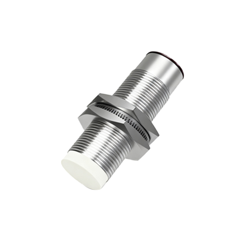
The most frequently encountered letter for proximity sensors is 'B'. According to common standards, the letter 'B' is designated for sensors, measuring, and detecting devices. Therefore, on a schematic, a proximity sensor might be labeled as 'B1', 'B10', 'BS1' (for a safety sensor), or similar. This 'B' group encompasses various sensor types, including inductive, capacitive, ultrasonic, and photoelectric (photo-eye) sensors, as they all serve the primary function of detection. In some older or region-specific notations, you might also see 'PR' or 'PX' used as an abbreviation for "proximity" directly. However, within the framework of standardized function codes, 'B' is the principal identifier. It's important to distinguish this from the letter 'S', which is generally reserved for switches (like manual pushbuttons, limit switches), though a mechanical limit switch with a roller lever is also a detecting device, blurring the lines slightly in practice.
Breakdown by Sensor Technology
While the function letter 'B' is common, additional suffixes or prefixes often specify the technology. An inductive proximity sensor, which detects metallic objects, might be specifically labeled 'BI' or 'B-IN' in more descriptive schematics. A capacitive sensor (detecting non-metallic materials) could be 'BC' or 'B-CAP'. Photoelectric sensors are frequently denoted with a reference to light, such as 'BE' (for emitter) and 'BR' (for receiver) in through-beam setups, or simply 'BPS' for a photoelectric sensor. Magnetic proximity sensors (reed switches) might use 'B' or sometimes 'SM' (switch, magnetic). These secondary codes are not always universally standardized at the same level as the primary function letter and can vary between manufacturers and engineering firms.
Symbols in Electrical Schematics
Beyond letters, the graphical symbol is key. The standard symbol for a proximity sensor (non-contact) often resembles a switch symbol (a circle with a diagonal line) but is enclosed within a diamond shape. This diamond indicates a "logic" or "electronic" function, distinguishing it from a mechanical switch. Inside or next to this diamond, the letter 'B' is placed. The type of sensor is sometimes implied by additional markings: two concentric circles might indicate an inductive type, while a light beam icon denotes a photoelectric sensor. The output type is shown by the nature of the switch inside the diamond: a standard opening/closing contact for digital (PNP/NPN) outputs. The connection points are usually marked as '+V' (power supply), '0V' (common), and 'OUT' (signal output).
Practical Examples in Ladder Logic and Nameplates
In PLC ladder logic diagrams, a proximity sensor appears as a normally open (NO) or normally closed (NC) contact instruction. Its address or tag name will incorporate the identification code. For instance, a sensor on input module 1, terminal 3, might be addressed as 'I:1/3', but its descriptive tag could be 'B3_PART_PRESENT'. On the physical sensor's nameplate, you will find a model number, but also often a terminal designation like 'B1' for the brown wire (positive), 'B2' for the blue wire (negative/0V), and 'B4' for the black wire (output). This 'B' on the terminal strip directly correlates to the function code, signifying it is part of a sensing device. Understanding this cross-reference between schematic symbol, letter code, ladder logic tag, and physical terminal marking is essential for efficient wiring and debugging.
Importance of Standardization and Documentation
Adherence to these letter codes and symbols is not merely academic. It ensures clarity