Introduction to Retroreflective Photoelectric Sensors
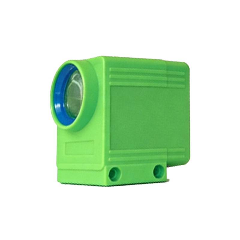
Retroreflective photoelectric sensors, often referred to as retro sensors, are a fundamental component in industrial automation and control systems. These devices operate by emitting a beam of light, typically from an LED or laser source, towards a specialized reflector. The reflector, designed to return light directly to its source regardless of the angle of incidence, bounces the beam back to the sensor's receiver. The sensor detects the presence or absence of an object by monitoring the status of this returned light beam. When an object interrupts the beam between the sensor and the reflector, the received light intensity drops, triggering a change in the sensor's output signal. This simple yet robust principle makes them exceptionally reliable for detection tasks where mounting a separate emitter and receiver is impractical. Their design offers a significant advantage over through-beam sensors by requiring wiring on only one side of the detection point, simplifying installation and reducing cost. Common applications include object detection on conveyor belts, pallet positioning, door and gate control, and people counting in various automated environments.
Key Factors Influencing Sensing Distance
The nominal sensing distance specified in a sensor's datasheet is a theoretical maximum under ideal conditions. In practical applications, several critical factors can significantly alter the effective range. The most prominent factor is the target object's characteristics. Size, color, and surface texture directly impact the amount of light reflected. A large, matte white object may be detectable at a greater distance than a small, glossy black object. Environmental conditions pose another major influence. Ambient light, particularly strong sunlight or light from other industrial sources, can flood the receiver and reduce sensitivity. Airborne contaminants like dust, fog, or steam can scatter and attenuate the light beam, shortening the effective range. The condition and alignment of the retroreflector are equally crucial. A dirty, scratched, or misaligned reflector will not return the full intensity of the light beam, degrading performance. Finally, the sensor's own specifications—such as light source type (red LED, infrared LED, or laser), lens quality, and receiver sensitivity—fundamentally determine its baseline capability. Understanding and mitigating these variables is essential for reliable system design.
Calculating and Applying the Distance Margin
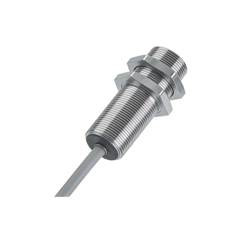
To ensure reliable operation under non-ideal conditions, engineers must apply a safety factor known as the distance margin or derating factor. This is not a single calculation but a process of conservative design. The first step is to select a sensor with a nominal sensing distance that is 1.5 to 3 times greater than the actual required application distance. This margin compensates for potential reductions caused by dirty optics, unfavorable target properties, or environmental interference. For example, if an object must be detected at 2 meters, choosing a sensor rated for 4 to 6 meters is a prudent starting point. Furthermore, the sensor should be installed and aligned with precision, ensuring the beam strikes the center of the reflector perpendicularly. Regular maintenance schedules should be established to clean the sensor's lens and the reflector surface. For challenging environments with high ambient light, selecting sensors with modulated light (often a pulsed infrared beam) and synchronous detection circuits is critical. These sensors ignore constant ambient light and only respond to their own modulated signal, greatly enhancing immunity to interference and stabilizing the effective sensing distance.
Advanced Technologies for Extended and Stable Ranges
Manufacturers continuously develop technologies to push the boundaries of sensing distance and stability. Laser-based retroreflective sensors represent a significant advancement, offering extremely focused beams that enable very long sensing distances—sometimes exceeding 100 meters—with high precision and minimal beam dispersion. Background suppression technology, while more common in diffuse sensors, has variants applied to retroreflective models to help ignore distant background reflections. Polarization filters are a classic and highly effective solution for a common problem: detecting shiny objects. A polarized lens on the emitter and a cross-polarized filter on the receiver ensure that only light that has made the round trip to the retroreflector and back (which loses its polarization) is detected. Light reflected directly off a glossy object retains its polarization and is rejected, preventing false triggers. For the most demanding applications involving transparent objects like glass or plastic films, sensors with special "transparent object detection" modes adjust sensitivity and timing to reliably detect these challenging targets without being confused by the reflector behind them.
Practical Installation and Troubleshooting Guidelines
Correct installation is paramount for achieving the published sensing distance. The sensor and reflector must be mounted on stable surfaces to prevent vibration-induced misalignment. They should be positioned so that the path is clear of potential obstructions and periodic contaminants. During alignment, use the sensor's built-in indicator (often an LED) or an ammeter connected to the output to maximize the signal strength. A common issue is "failure to detect" at expected distances. The troubleshooting sequence should begin with verifying power and wiring, then cleaning the lens and reflector. Next, check for precise alignment and ensure the object is fully interrupting the beam path. Measure the actual light intensity received, if the sensor provides this diagnostic, and compare it to the threshold. If ambient light is suspected, temporarily shield the path. Another frequent problem is unstable operation or chattering output, which often points to a marginal received signal strength, interference from reflective surfaces near the beam path, or a faulty reflector. Incrementally reducing the installed sensing distance by moving the sensor closer to the target area often resolves marginal performance issues and provides a more robust solution.