Introduction to Two-Wire Proximity Sensors
Two-wire proximity sensors are fundamental components in industrial automation, widely used for non-contact detection of metallic objects. Unlike three-wire or four-wire sensors, these devices simplify wiring by combining power supply and signal output into a single pair of wires. This design reduces installation complexity and cost, making them ideal for applications where space and budget are constrained. Typically, two-wire sensors operate on DC or AC voltage, with the load (such as a PLC input or relay) connected in series. Their robust construction ensures reliable performance in harsh environments, including areas with dust, moisture, or vibration. Understanding their working principle is essential for engineers to optimize system design and troubleshoot issues effectively.
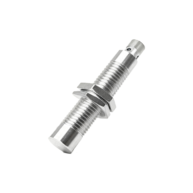
Basic Operating Principle
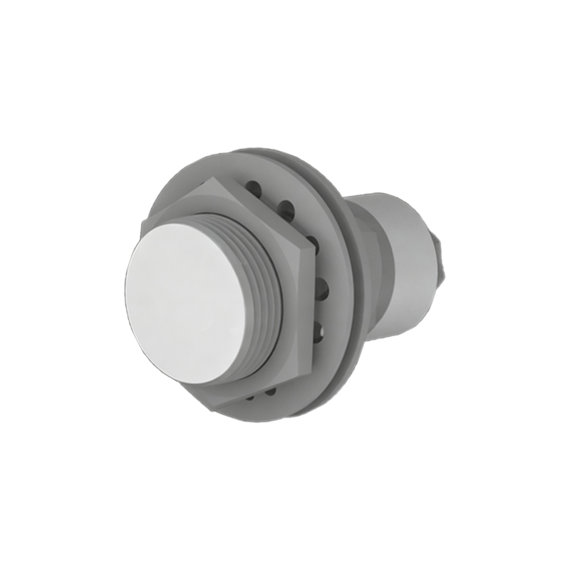
The core function of a two-wire proximity sensor involves detecting the presence or absence of a target object without physical contact. It relies on electromagnetic fields generated by an oscillator circuit. When a metallic object enters the sensor's detection range, it disturbs the electromagnetic field, causing changes in oscillation amplitude or frequency. This alteration is processed by an evaluation circuit, which triggers a switching action. In two-wire configurations, the sensor modulates current flow through the same wires used for power. When no target is detected, a small leakage current (often a few milliamps) flows to keep the sensor active. Upon detection, the current increases significantly to drive the connected load, indicating an "on" state. This current-based signaling eliminates the need for separate output wires, streamlining the setup.
Internal Circuit Diagram and Components
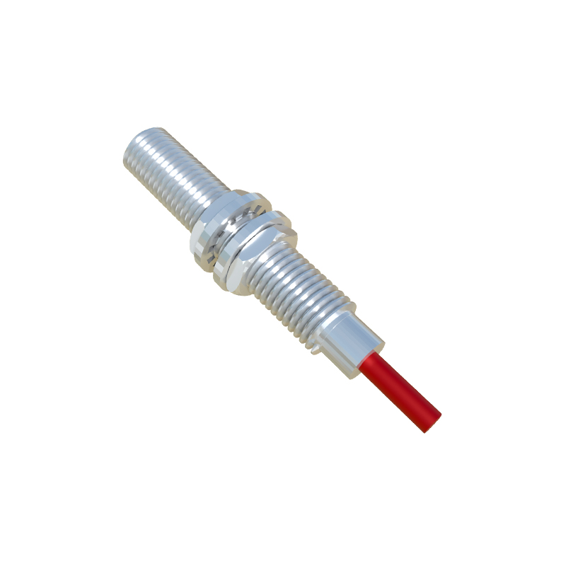
A typical two-wire proximity sensor comprises several key components integrated into a compact housing. The oscillator generates a high-frequency electromagnetic field at the sensing face, usually using a coil and capacitor. The demodulator converts oscillations into a DC signal, which is fed to a trigger circuit. The trigger compares this signal to a preset threshold and activates a solid-state switch (like a transistor or thyristor) when the threshold is exceeded. A protection circuit safeguards against overvoltage, reverse polarity, and short circuits. In the diagram, the two wires connect directly to the power supply and load in series. During idle state, the sensor draws minimal "off-state" current to maintain operation. When activated, the switch closes, allowing higher "on-state" current to flow, which powers the load. This design ensures energy efficiency and compatibility with various control systems.
Wiring and Connection Methods
Proper wiring is crucial for the reliable operation of two-wire proximity sensors. They can be connected in either sourcing (PNP) or sinking (NPN) configurations, depending on the application's electrical requirements. In sourcing mode, the sensor acts as a current source, with the load connected between the output and ground. Conversely, in sinking mode, the sensor sinks current to ground, with the load linked to the positive supply. The wiring diagram typically shows two terminals: one for power (L+) and one for load (L-). It's vital to match the sensor's voltage rating (e.g., 10-30V DC or 20-250V AC) with the power source. Additionally, a protective device like a fuse or circuit breaker should be included to prevent damage from overloads. Engineers must ensure correct polarity for DC sensors and verify load compatibility to avoid malfunction or premature failure.
Advantages and Limitations
Two-wire proximity sensors offer notable benefits in industrial settings. Their simplified wiring reduces installation time and material costs, while the absence of extra output lines minimizes clutter in control panels. They are inherently safe for use in explosive environments when properly rated, as lower current levels decrease spark risk. However, limitations exist. The leakage current in the off-state can cause issues with highly sensitive loads, potentially leading to false triggering. Voltage drop across the sensor may affect performance, especially with long cable runs or high loads. Additionally, these sensors generally have slower response times compared to three-wire versions, making them less suitable for high-speed applications. Understanding these trade-offs helps in selecting the right sensor type for specific operational needs.
Common Applications and Industry Use Cases
Two-wire proximity sensors are versatile tools across various industries. In manufacturing, they detect parts on conveyor belts, monitor machine tool positions, and count products in assembly lines. Automotive plants use them for robotic arm positioning and safety interlocking on presses. Packaging machinery relies on them for material presence sensing and fill-level control. In building automation, they secure doors and elevators by detecting metal components. Their rugged design makes them suitable for outdoor applications like vehicle detection in parking systems or metal sorting in recycling facilities. By providing reliable, maintenance-free operation, these sensors enhance efficiency