Understanding Switching Frequency Fundamentals
The switching frequency of a photoelectric sensor, often expressed in Hertz (Hz), is a critical performance parameter that defines the maximum number of detection operations the sensor can perform per second. In essence, it quantifies the sensor's speed. A higher switching frequency allows the sensor to detect objects moving at higher velocities or objects placed very close together on a fast-moving conveyor. For engineers, selecting a sensor with an appropriate switching frequency is paramount to ensuring system reliability and preventing missed counts or faulty process triggers. The frequency is inherently limited by the time required for the sensor's internal components—primarily the light emitter, receiver, and evaluation electronics—to complete one full cycle of sending a light pulse, receiving the reflected or interrupted signal, processing it, and switching the output state.
Key Factors Influencing Maximum Frequency
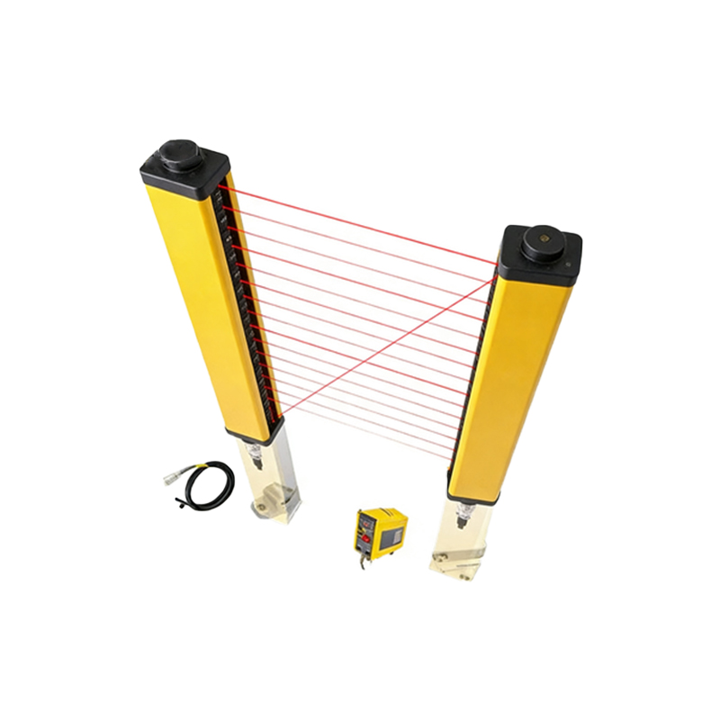
Several design and application factors directly impact the achievable switching frequency. The type of photoelectric sensor plays a significant role. Diffuse reflective sensors, which rely on light bouncing off the target, typically have lower maximum frequencies compared to through-beam or retro-reflective models. This is due to the weaker signal strength and more complex signal processing required. The response time, a complementary specification usually listed in milliseconds, is the inverse of the switching frequency. A sensor with a 1 ms response time can theoretically achieve a 1 kHz switching frequency. Furthermore, the detection mode (light-on or dark-on), the selected output type (PNP/NPN transistor, analog), and any built-in functions like timers or logic operations can add processing delay, thereby reducing the effective operational frequency.
Through-Beam vs. Diffuse: A Frequency Comparison
Through-beam sensors, consisting of separate emitter and receiver units, generally offer the highest switching frequencies, often ranging from 1 kHz to 5 kHz or even higher for specialized models. The clear, strong signal path allows for very fast and unambiguous detection. Retro-reflective sensors, which use a reflector, also achieve high frequencies but may be slightly lower due to potential alignment issues. Diffuse reflective sensors, where the emitter and receiver are in one housing, typically have lower maximum frequencies, often between 100 Hz and 1 kHz. The frequency can be further affected by the target's properties; a small, dark, or non-reflective object requires more sensitive (and often slower) processing than a large, light-colored one, potentially forcing a reduction in the operational frequency setting for reliable detection.
Application Considerations and Calculation
Correctly matching the sensor's frequency to the application is essential. A critical calculation involves determining the required frequency based on object size and speed. The formula is: Required Switching Frequency (Hz) = Object Speed (m/s) / Object Length (m). For example, to detect packages 50 mm (0.05 m) long moving at 2 m/s on a conveyor, the required frequency is 2 / 0.05 = 40 Hz. It is standard engineering practice to apply a safety factor of at least 2, so a sensor with a minimum frequency of 80 Hz should be selected. For high-speed sorting, small part counting, or registration mark detection on printing presses, sensors with frequencies in the kilohertz range are mandatory to ensure precision and avoid system bottlenecks.
Technical Limitations and Signal Stability
Pushing a sensor to its maximum rated switching frequency may come with trade-offs. Operating at the limit can reduce the stability margin for the received light signal, making the sensor more susceptible to electrical noise, ambient light interference, or minor fluctuations in supply voltage. This can lead to false triggering. Many modern sensors feature adjustable response time or switching frequency settings. In noisy environments or with challenging targets, it is often advisable to slightly reduce the frequency setting to gain a more robust and stable signal. Additionally, the sensor's light source modulates at a specific frequency to combat ambient light; this carrier frequency is different from the switching frequency but is a foundational element that enables the high-speed, noise-immune operation of AC-operated sensors.
Selecting the Right Sensor for High-Speed Tasks
When specifying a sensor for high-frequency applications, engineers must look beyond the headline switching frequency number. Key specifications to cross-reference include the response time, the repeat accuracy, and the sensor's minimal detectable object size at the intended sensing distance and speed. Data sheets often provide graphs showing the relationship between switching frequency, sensing distance, and object contrast. Fiber optic photoelectric sensors, due to their small sensing head and fast electronics, are frequently the choice for ultra-high-speed applications like detecting leads on integrated circuits or monitoring fast-rotating gears. Always consult the manufacturer's technical documentation and consider performing real-world tests under expected operating conditions to validate performance before final system integration.