Introduction to 4-Wire Photoelectric Sensors
In the realm of industrial automation, photoelectric sensors are indispensable for non-contact detection, counting, and positioning. Among the various configurations, the 4-wire photoelectric sensor stands out for its unique operational characteristics and wiring simplicity. Unlike their 2-wire or 3-wire counterparts, 4-wire sensors provide distinct, isolated paths for power supply and output switching. This design typically features two wires for the power supply (usually a DC voltage like 12-24V DC) and two wires for the output signal. The output can be configured as either a normally open (NO) or normally closed (NC) contact, or sometimes as complementary outputs (one NO and one NC), offering greater flexibility in control circuit design. This separation ensures that the load current does not interfere with the sensor's internal circuitry, leading to more stable and reliable performance, especially when driving inductive loads like relays or solenoids.
Internal Circuitry and Operating Principle
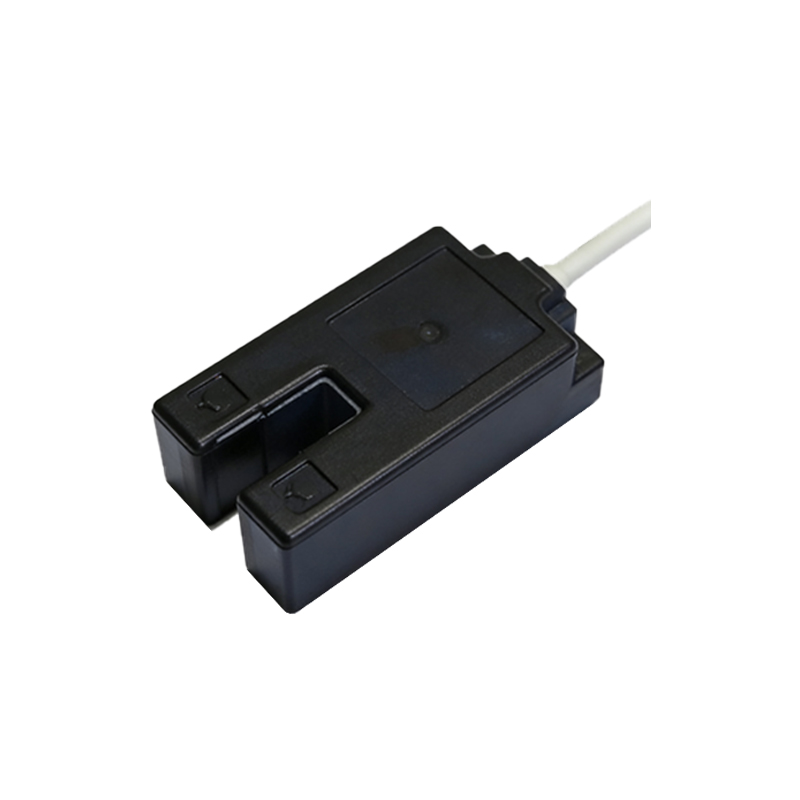
The core of a 4-wire sensor consists of three main components: an emitter (light source), a receiver, and a solid-state switching element. The emitter, often an LED, projects a beam of light—visible red, infrared, or laser. The receiver detects this light. When an object interrupts or reflects this beam (depending on the sensing mode: through-beam, retro-reflective, or diffuse), the receiver's state changes. This change is processed by the internal amplifier. In a 4-wire DC sensor, the amplifier then controls a solid-state switch, typically a MOSFET or a transistor. The key distinction is that the switch is connected to the two output wires, which are completely separate from the two power input wires. This allows the output to switch a load connected to a different voltage source, if necessary, although it is most commonly connected to the same DC supply. The output acts as a dry contact, making it highly versatile for interfacing with Programmable Logic Controllers (PLCs), counters, and other control devices.
Wiring Configuration and Color Codes
Correct wiring is paramount for safe and functional operation. While color codes can vary by manufacturer, a common standard for DC 4-wire sensors is as follows: Brown wire connects to the positive DC supply voltage (+V). Blue wire connects to the common negative or 0V DC supply. Black wire is the output signal (usually the normally open output). White wire is often the complementary output (normally closed) or a second output function. It is crucial to consult the specific sensor's datasheet. The load (e.g., a PLC input, relay coil, or indicator lamp) is connected in series with the output wires. For instance, to use the black (NO) output, one side of the load is connected to the positive supply, and the other side is connected to the black wire. The blue wire completes the circuit back to the negative supply. This isolated design prevents ground loops and minimizes electrical noise interference, which is critical in industrial environments with heavy machinery.
Key Advantages Over 2-Wire and 3-Wire Sensors
The 4-wire design offers several compelling benefits. First, it provides electrical isolation between the sensor's power circuit and the output switching circuit. This protects the sensitive internal electronics from voltage spikes or back-EMF generated by the load. Second, it allows for a wider range of load types, including both DC and, with appropriate models, AC loads, without requiring external protective diodes for inductive loads. Third, the leakage current in the "off" state is virtually zero, which prevents false triggering in highly sensitive PLC input modules—a common issue with some 2-wire AC sensors. Fourth, the availability of both NO and NC outputs from a single device saves space and simplifies control logic. Compared to a 3-wire sensor (which has common, power, and one output), the 4-wire version offers that additional output flexibility and often more robust switching capability.
Common Industrial Applications and Selection Criteria
Four-wire photoelectric sensors are deployed across diverse industries. In packaging lines, they detect the presence of boxes on a conveyor. In automotive assembly, they verify the correct placement of components. In material handling, they count bottles or cans. Their robust output is ideal for directly controlling small relays, solenoids, or lamps without an intermediate amplifier. When selecting a 4-wire sensor, engineers must consider several factors: Sensing range and mode (through-beam for long range, diffuse for proximity, retro-reflective for easy alignment). Light source type (laser for precision, infrared for immunity to ambient light). Output current rating (ensure it exceeds the load's requirement). Supply voltage range. Environmental rating (IP67 or higher for washdown or dusty areas). Response time for high-speed applications. The isolated output makes them particularly suitable for applications where the load circuit must be electrically separate from the control logic for safety or noise immunity reasons.
Troubleshooting and Maintenance Best Practices
Effective troubleshooting begins with a systematic approach. First, verify the power supply voltage at the sensor's terminals using a multimeter. Next, check the output state. Many sensors have a built-in LED indicator that shows power and output status. If the sensor indicates detection but the load does not activate, use the multimeter to measure voltage across the output wires under load conditions to see if the switch is functioning. Ensure the load is within the sensor's specified current and voltage ratings. Common issues include misalignment, dirty lenses, incorrect sensing mode for the target object (e.g., detecting a shiny surface with a diffuse sensor), or electrical interference. For maintenance, regularly clean the lens with a soft cloth. Ensure wiring connections are tight and not corroded. Periodically verify the sensing reliability by introducing a test object. Keeping spare sensors on hand for critical processes minimizes downtime.
Future Trends and Integration with Industry 4.0
The evolution of 4-wire photoelectric sensors is closely tied to smart manufacturing trends. Modern iterations now feature IO-Link communication capability, adding a digital communication layer to the traditional switching wires. This allows for parameter setting, remote monitoring, and advanced diagnostics (e.g., reporting lens contamination or temperature warnings) without changing the simple 4-wire interface for the primary switching function. Furthermore, sensors are becoming more robust, with higher ingress protection ratings and enhanced resistance to environmental factors like welding glare or coolant sprays. The integration of advanced optics and algorithms is enabling background suppression and precise color detection in a standard housing. As Industry 4.0 progresses, the reliable, isolated switching of the 4-wire sensor will remain a fundamental physical layer, increasingly augmented by digital intelligence for predictive maintenance and seamless data integration into broader control systems.