Understanding False Triggering in Photoelectric Sensors
False triggering, or erroneous signal output, is a persistent challenge in industrial automation systems utilizing photoelectric sensors. This phenomenon occurs when a sensor detects an object or condition it was not intended to detect, or fails to detect the intended target, leading to incorrect process control, machine stoppages, or product quality issues. At its core, false triggering is a signal integrity problem. Photoelectric sensors operate on the principle of emitting a light beam—typically infrared, visible red, or laser—and detecting changes in the received light. Any external factor that interferes with this light path or mimics the intended target's signal can cause a false event. Common manifestations include a sensor triggering without a target present, failing to trigger when a target is present, or providing intermittent and unreliable readings. Understanding the fundamental mechanisms of light emission, reception, and environmental interaction is the first critical step in developing robust prevention strategies.
Primary Causes of Erroneous Signals
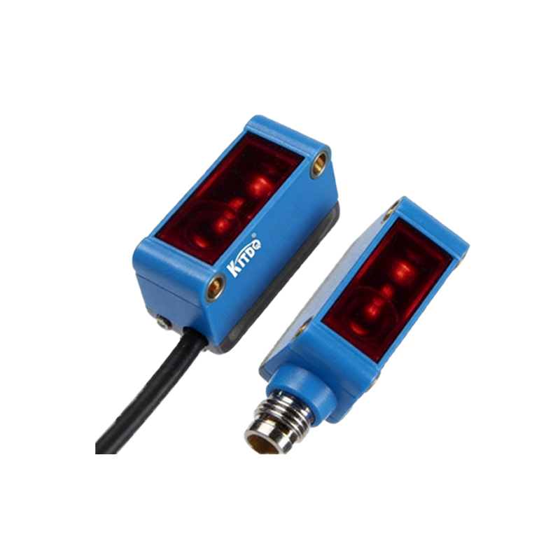
Identifying the root cause is essential for implementing an effective solution. The primary culprits of false triggering can be categorized into environmental, mechanical, and electrical factors. Environmental interference is often the most significant. Ambient light, especially direct sunlight or strobe lighting from welding equipment, can flood the sensor's receiver, saturating it and preventing it from seeing the emitted beam. Dust, steam, fog, or oil mist can scatter or attenuate the light beam, reducing signal strength. Vibrations can cause momentary misalignment between the emitter and receiver in through-beam sensors or alter the reflection angle in reflective models. Mechanically, buildup of debris on the sensor's lens acts as an opaque barrier, while condensation can refract the light unpredictably. Electrically, electromagnetic interference (EMI) from nearby motors, variable frequency drives (VFDs), or power lines can induce noise in the sensor's circuitry or cabling, corrupting the signal. Even power supply fluctuations or ground loops can lead to unstable operation.
Selecting the Right Sensor Type and Technology
Prevention begins at the design and selection stage. Choosing the appropriate sensor type for the application is paramount. Through-beam sensors, with separate emitter and receiver units, offer the longest sensing ranges and highest immunity to target color, reflectivity, and surface angle. They are generally more reliable for precise detection but require careful alignment. Retro-reflective sensors use a reflector and are easier to install, but can be triggered by any shiny surface entering their field of view. Diffuse or proximity sensors are self-contained and detect light reflected directly from the target, making them susceptible to variations in target color and texture. For challenging environments, consider specialized models. Sensors with modulated (pulsed) LED light and synchronous detection circuits are inherently immune to ambient light. Polarized filters on retro-reflective sensors can ignore false signals from ordinary shiny objects. Background suppression sensors use triangulation to detect only objects within a precise distance window, ignoring objects beyond the set background. Laser-based sensors provide a very precise, narrow beam ideal for small part detection or long ranges in clear environments.
Optimal Installation and Alignment Techniques
Proper installation is a critical, often overlooked, defense against false triggers. For through-beam sensors, precise alignment is non-negotiable. Use alignment tools provided by the manufacturer and secure both emitter and receiver in rigid, vibration-resistant mounts. Avoid mounting sensors where they are subject to mechanical shock or where thermal expansion of the machine frame could shift alignment. Position sensors to minimize exposure to direct ambient light; use physical shrouds or tubes to create a protected light path. Angle the sensor slightly so that its lens is not parallel to potential sources of contamination, allowing debris to fall away. Ensure the sensing path is clear of temporary obstructions like passing personnel, forklifts, or swinging cables. For diffuse sensors, be mindful of the sensing field and potential background objects. Always follow the manufacturer's specified sensing distance (Sn) and leave a safety margin. After installation, perform a thorough commissioning test, simulating worst-case conditions like accumulated dust or dim lighting.
Implementing Environmental Protections and Filtering
When environmental factors cannot be avoided, additional protective measures are required. Install protective housings or air curtains with clean, dry air blowing across the sensor lens to keep it free of dust, chips, and moisture. For applications with heavy particulate, consider sensors specifically rated with an IP67 or IP69K ingress protection rating. To combat electrical noise, use shielded cables and connect the shield properly to a stable earth ground at the controller end, avoiding ground loops. Keep sensor cables away from power cables, motor leads, and other sources of EMI; if crossing is necessary, do so at a 90-degree angle. Employ electrical filters, which are often built into the sensor or programmable via teach-in buttons or software. These filters, such as a delay-on or delay-off function, require the target to be present (or absent) for a set time before the output changes, effectively ignoring brief transients. Many modern sensors also feature automatic sensitivity adjustment or teach-in functions to adapt to slowly changing conditions like lens dirtying.
Routine Maintenance and Diagnostic Monitoring
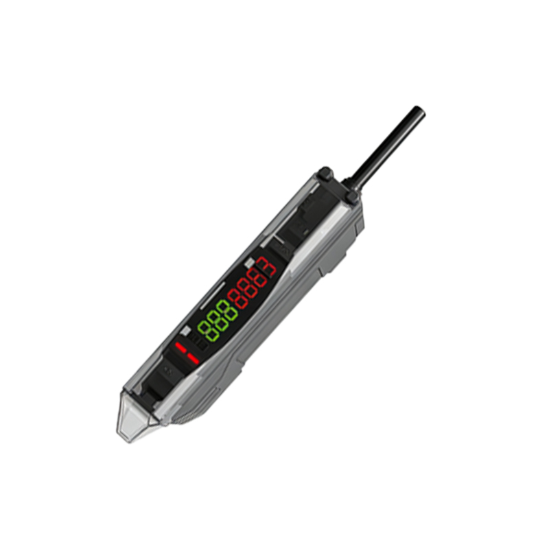
A proactive maintenance regimen is the final layer of defense. Establish a schedule for visually inspecting and cleaning sensor lenses with appropriate, non-abrasive cleaners. Check for physical damage, loose mounting hardware, and cable integrity. Monitor the sensor's performance indicator, often a green/red LED that shows signal strength or stability. Many advanced sensors offer IO-Link or other digital communication, providing valuable diagnostic data such as operating hours, signal strength percentage, temperature warnings, and contamination alerts. This data can be used for predictive maintenance, scheduling cleaning before a failure occurs. Periodically re-validate sensor alignment and functionality, especially after any maintenance on the surrounding machinery. Keeping a log of false triggering incidents, along with environmental conditions at the time, can reveal patterns and point to systemic issues that require a more permanent engineering solution, such as relocating the sensor or changing its type.