Understanding Proximity Sensor Fundamentals
Proximity sensors are indispensable components in modern industrial automation, providing non-contact detection of metallic or non-metallic objects. Their operation hinges on generating an electromagnetic field or beam of radiation. When a target object enters this field, it causes a change in the sensor's oscillation or signal return, which is then converted into an electrical output signal. This fundamental principle allows for reliable, wear-free operation in harsh environments where mechanical switches would fail. The core types include inductive sensors for metals, capacitive sensors for various materials including liquids, and photoelectric sensors using light beams. Selecting the correct sensor is the critical first step before any wiring can commence, as the electrical characteristics and requirements differ significantly between types and models.
Power Supply Connections and Considerations
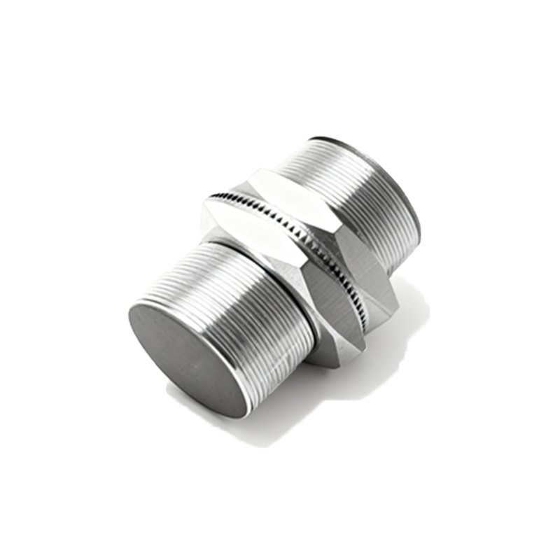
The cornerstone of any proximity sensor installation is a stable and appropriate power supply. Most industrial DC sensors operate on 10-30V DC, while AC variants are commonly rated for 90-250V AC. The sensor's datasheet is the ultimate authority for voltage and current ratings. Wiring begins with connecting the positive voltage line (often brown or red) to the designated V+ or L+ terminal and the negative or neutral line (often blue or black) to the 0V or L- terminal. It is paramount to ensure the power supply is properly fused and, for DC systems, observe correct polarity to prevent immediate damage. For sensors in high-noise environments, such as those near variable frequency drives or welding equipment, using a separate, shielded power cable or installing noise filters is highly recommended to prevent erratic switching.
Output Configuration and Load Wiring
Proximity sensor outputs are typically categorized as NPN (sinking) or PNP (sourcing) for DC models, and NO (Normally Open) or NC (Normally Closed) for both AC and DC. An NPN sensor switches the negative (0V) line to the load, while a PNP sensor switches the positive voltage line. The load—a PLC input, relay coil, or indicator lamp—is connected between the sensor's output wire (usually black) and the opposite supply rail. For instance, with a PNP sensor, one side of the load connects to the black output wire, and the other side connects to 0V. It is crucial to verify the sensor's maximum output current to ensure it is not exceeded by the load's inrush or steady-state current, which could lead to failure. Always include a protective flyback diode across inductive loads like relay coils to suppress voltage spikes.
Wiring for Specific Output Types
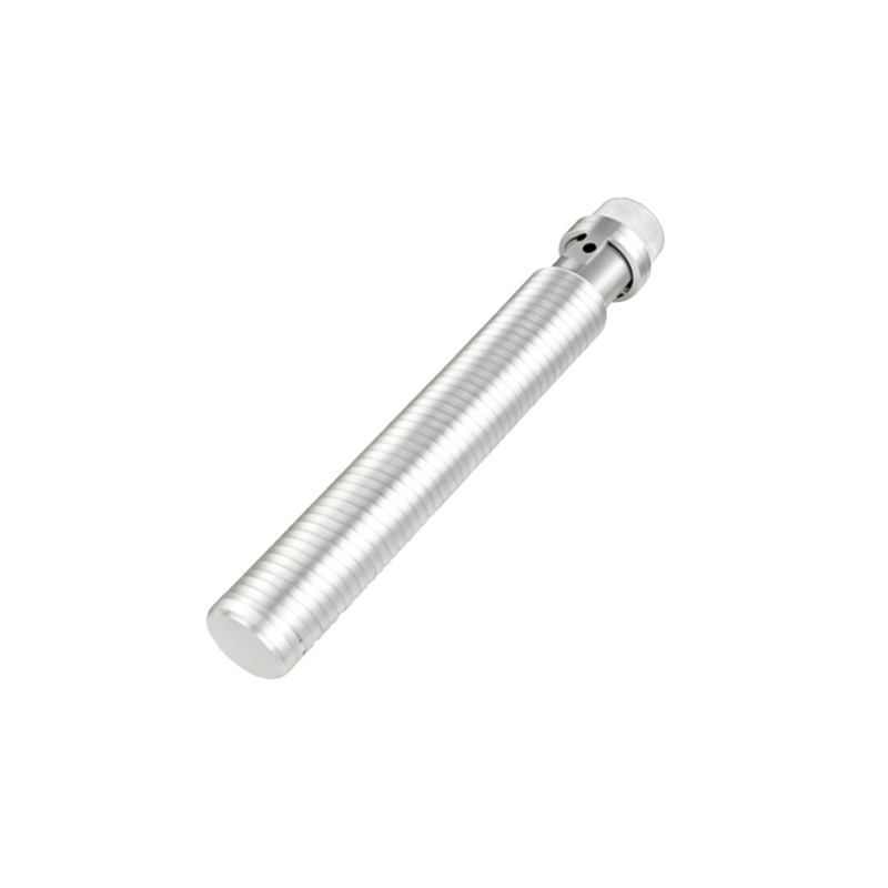
Beyond standard two-wire and three-wire sensors, more complex configurations exist. Analog output sensors (e.g., 4-20mA or 0-10V) require connection to a compatible analog input card. The current loop must be completed by wiring the sensor's positive, negative, and signal wires to the corresponding terminals on the controller. For sensors with IO-Link digital communication, wiring involves power connections (V+ and 0V) plus a third communication wire that carries both the switched signal and the digital data stream on a single line. This requires an IO-Link master device. Push-pull or complementary output sensors have two output wires that switch alternately; these are often used in safety-critical applications to detect wiring faults and must be connected to a specialized evaluating circuit.
Shielding, Grounding, and Noise Mitigation
Proper shielding and grounding are non-negotiable for reliable sensor operation, especially for capacitive and analog sensors susceptible to electrical interference. The cable shield, typically a braided or foil layer, should be connected to a stable earth ground at the control panel end only, creating a drain path for noise. Avoid grounding both ends, as this can create ground loops that induce current and cause instability. Keep sensor cables separate from high-voltage power lines; if they must cross, do so at a 90-degree angle to minimize inductive coupling. For long cable runs exceeding the manufacturer's recommendation, consider using a relay or repeater module close to the sensor to boost the signal and prevent voltage drop or signal degradation.
Diagnosing Common Wiring Issues
Even with careful installation, issues can arise. A sensor that fails to power on often indicates reversed polarity, a blown fuse, or excessive voltage drop over long wires. Intermittent operation or reduced sensing distance frequently points to electrical noise interference, necessitating a review of shielding and grounding practices. If a sensor appears to be "stuck on," it could be due to sensor overload (exceeding max current), a short circuit in the load wiring, or, in the case of inductive sensors, detection of a nearby metal object like a mounting bracket. A systematic approach using a mult