Understanding Glass Proximity Sensor Fundamentals
Glass proximity sensors are critical components in modern automation and consumer electronics, often used for touchless control, object detection, and safety applications. Unlike metallic-housed sensors, these utilize a glass face, typically for applications requiring chemical resistance, food-grade compliance, or specific optical clarity. The core principle remains based on electromagnetic fields (inductive or capacitive) or optical (infrared) technology. Inductive sensors detect metallic objects, capacitive sensors detect both metallic and non-metallic objects by measuring changes in capacitance, and optical sensors use an infrared LED and phototransistor. Understanding the underlying technology—whether it's a capacitive sensor behind a glass panel or an optical sensor with a glass lens—is the first crucial step before testing. Misidentification can lead to incorrect testing procedures and faulty diagnostics.
Essential Tools and Safety Precautions
Before initiating any test, gather the appropriate tools. A digital multimeter (DMM) capable of measuring DC voltage, current, and resistance is indispensable. An oscilloscope is highly recommended for analyzing signal integrity and response times, especially for PWM or analog output sensors. For optical sensors, an IR receiver card or a dedicated sensor tester can be invaluable. Always consult the manufacturer's datasheet for the specific sensor model to identify pinouts, supply voltage ranges (commonly 10-30V DC or 5V DC), output types (PNP/NPN, analog, IO-Link), and switching current. Safety is paramount. Ensure the system is powered down before making any physical connections. When working with glass sensors, handle the glass face with care to avoid cracks or chips that can compromise integrity, especially in washdown or harsh environments. Use appropriate personal protective equipment if the sensor is installed in an industrial setting.
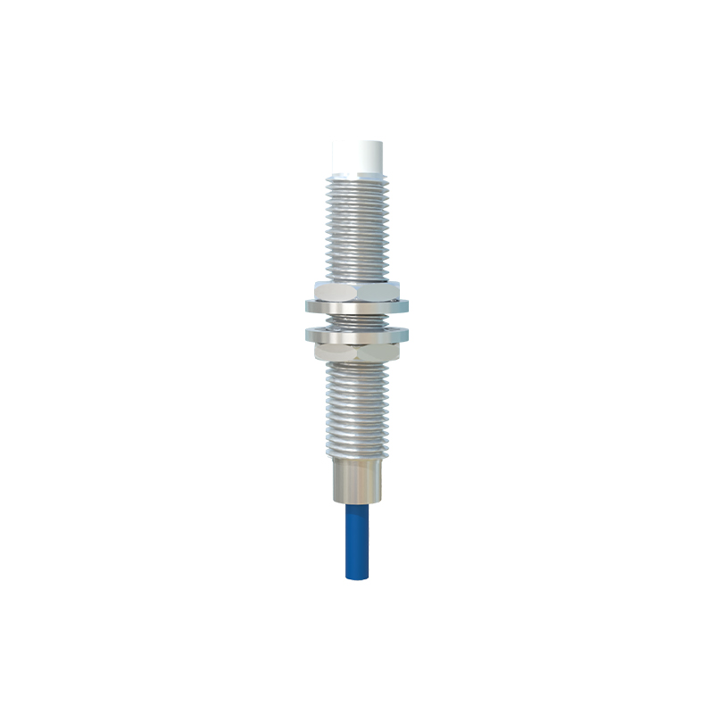
Visual and Physical Inspection
Begin with a thorough visual inspection. Examine the glass surface for any cracks, deep scratches, or cloudiness. Check for moisture ingress or condensation between the glass and the sensing element, which is a common failure point. Inspect the housing and cable entry for integrity. Verify the tightness of the mounting and the cleanliness of the glass surface. Contaminants like oil, dust, or adhesive residues can severely affect performance, particularly for capacitive and optical types. A clean, lint-free cloth with an appropriate cleaner (like isopropyl alcohol for glass) should be used to clean the surface. Ensure the sensor is correctly aligned and that the target object moves within the specified sensing range and approach axis.
Testing Power Supply and Wiring
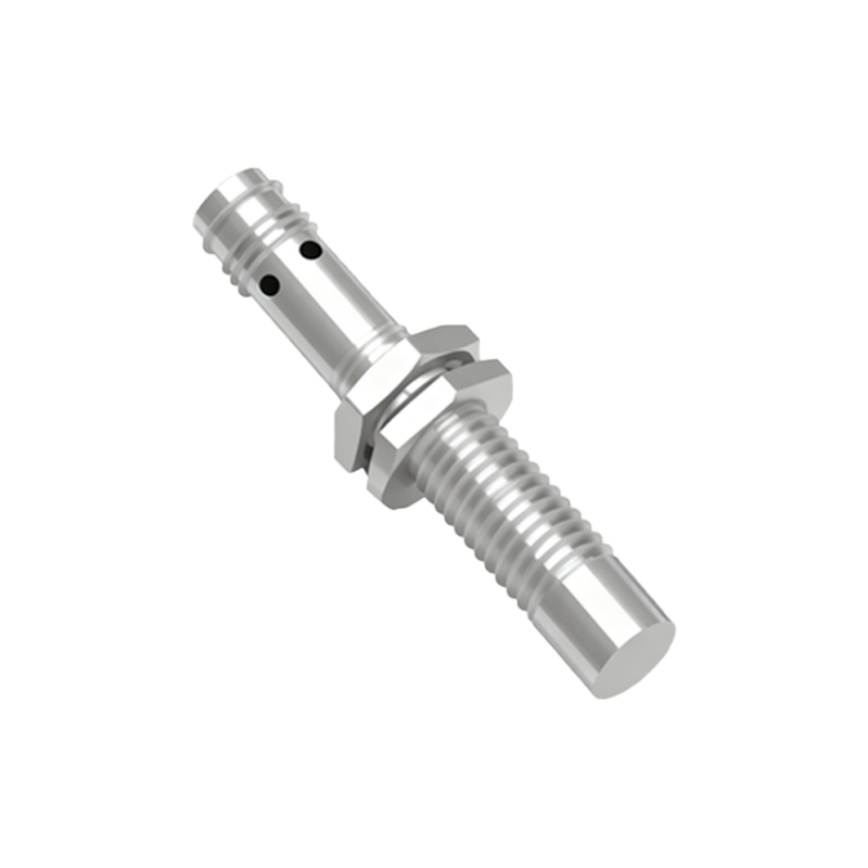
With power disconnected, use the multimeter in continuity or resistance mode to check for short circuits or open wires in the cable. Refer to the datasheet for the pin configuration. Reconnect power and measure the supply voltage at the sensor's terminals. Ensure it is stable and within the specified range, typically ±10%. A fluctuating or low voltage can cause erratic behavior. For a 3-wire DC sensor, identify the brown (V+), blue (V- or 0V), and black (output) wires. Measure the voltage between brown and blue to confirm supply. Next, with no target present, measure the voltage between the black output wire and the blue wire. For a PNP (sourcing) sensor, you should read near supply voltage when inactive (open) and near 0V when active (if a pull-down resistor is present, the reading might be different). For an NPN (sinking) sensor, the behavior is opposite.
Verifying Sensor Output and Functionality
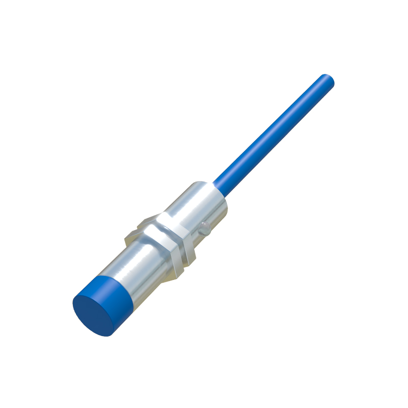
This is the core functional test. For a discrete (on/off) sensor, introduce a valid target object into the sensing field. For an inductive sensor, use the specified metal (e.g., mild steel). For a capacitive sensor, use a material like plastic or liquid as per its calibration. For an optical sensor, ensure you use an object that reflects or interrupts the IR beam appropriately. While the target is present, measure the output voltage again. A PNP sensor should switch to a high state (near supply voltage), and an NPN to a low state (near 0V). Listen for an audible click from a mechanical relay if used, or observe an LED indicator if the sensor is equipped with one. Using an oscilloscope, probe the output signal to check for clean switching transitions without excessive noise or bounce. For analog sensors, measure the output current (4-20mA) or voltage (0-10V) and verify it changes proportionally as the target distance changes.
Assessing Sensing Range and Hysteresis
Accurate range testing requires a calibrated setup. Mount the sensor securely. Using a valid target mounted on a linear scale, slowly move