Introduction to Photoelectric Sensor Connectors
Photoelectric sensor connectors are critical components in the signal chain of modern dynamic balancing machines. These specialized connectors serve as the primary interface between the photoelectric sensor, which detects rotational speed and phase reference marks on the rotor, and the balancing machine's central processing unit. The integrity of this connection directly influences the accuracy, repeatability, and reliability of unbalance measurement. In high-precision industrial environments, even minor signal degradation or intermittent connectivity can lead to significant measurement errors, costly rework, and production downtime. Therefore, selecting and maintaining the appropriate connector is not merely a peripheral concern but a fundamental aspect of system design and operational upkeep. This guide delves into the technical specifications, selection criteria, and maintenance protocols essential for optimizing performance.
Key Technical Specifications and Design Features
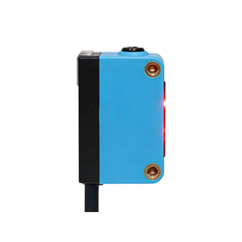
The design of photoelectric sensor connectors for balancing applications is driven by the need for signal fidelity and environmental robustness. Key specifications include the connector type, pin configuration, shielding effectiveness, and ingress protection rating. Common connector families used are miniature circular connectors (e.g., M8, M12 standards) or specialized subminiature varieties, often featuring a threaded coupling mechanism for secure mating in high-vibration environments. The pin configuration is typically simple, with dedicated pins for power supply, signal output, and ground. A critical design feature is integrated shielding within the connector body and cable to protect the low-voltage, high-impedance sensor signal from electromagnetic interference generated by nearby motors, drives, and power cables. The connector's housing material, usually a robust thermoplastic or metal, must withstand exposure to coolants, oils, and metal particulates common in machining and balancing workshops, necessitating an IP67 or higher rating for dust and fluid resistance.
Signal Integrity and Electrical Characteristics
Maintaining signal integrity from the sensor to the analyzer is paramount. The photoelectric sensor typically outputs a digital pulse train or a sinusoidal analog signal corresponding to the rotor's rotation and a once-per-revolution marker pulse. The connector and its attached cable must preserve the sharp rise and fall times of these pulses without introducing excessive capacitance, inductance, or resistance. Connectors with gold-plated contacts are preferred for their low contact resistance and corrosion resistance, ensuring a stable electrical connection over thousands of mating cycles. The characteristic impedance of the cable-connector assembly should match the sensor and receiver circuitry as closely as possible to prevent signal reflections. Furthermore, proper grounding schemes through the connector shell are essential to create a continuous shield that diverts noise away from the signal conductors, preventing false triggering or phase jitter in the balancing system.
Installation, Wiring, and Best Practices
Correct installation is crucial for long-term reliability. The process begins with careful cable preparation, ensuring the shield is properly terminated to the connector's backshell or designated grounding pin without creating a "pigtail," which can compromise shielding effectiveness. Strain relief features built into the connector must be correctly engaged to prevent axial forces or bending moments from being transferred to the solder joints or crimped terminals inside. When routing the sensor cable, it should be kept separate from power lines, preferably in dedicated cable trays or conduits, to minimize inductive coupling. The mating face of the connector should be kept clean and free of debris; a quick wipe with isopropyl alcohol is recommended before connection. Finally, the threaded coupling should be hand-tightened firmly to the specified torque to ensure environmental sealing and electrical continuity without damaging the threads or O-rings.
Common Failure Modes and Troubleshooting
Despite their robust design, connectors are frequent failure points. Common issues include intermittent signals, complete signal loss, or erratic balancing readings. Physical damage is a primary cause: broken cable strands due to excessive flexing, cracked connector housings from impact, or corroded pins from fluid ingress. Internally, fretting corrosion can occur on contact surfaces due to microscopic movement caused by vibration, leading to increased resistance. Troubleshooting should follow a systematic approach. First, visually inspect the connector, cable, and mating socket for obvious damage or contamination. Use a multimeter to check for continuity and resistance between pins. A more advanced method involves monitoring the signal waveform with an oscilloscope at the connector to identify noise, attenuation, or distortion. Often, simply reseating the connector can temporarily restore contact, but this usually indicates worn contacts that require replacement.
Selection Criteria for Specific Applications
Selecting the right connector requires analyzing the application's specific demands. For portable balancing machines used in field service, connectors with quick-disconnect features and superior mechanical ruggedness are vital. In integrated, high-speed production balancing stations, connectors must offer exceptional EMI/RFI shielding and may require locking mechanisms to prevent accidental disconnection from automated handling equipment. The operating environment dictates the material choice: stainless steel or brass with nickel plating for highly corrosive atmospheres, and high-temperature plastics for areas near heat sources. It is also essential to consider the supply chain; choosing a connector from a reputable manufacturer with available technical support and a reliable stock of mating components, cables, and repair kits minimizes future downtime. Compatibility with the existing sensor and machine interface is, of course, a non-negotiable prerequisite.
Future Trends and Conclusion
The evolution of photoelectric sensor connectors parallels advancements in industrial connectivity. Trends point towards miniaturization without sacrificing performance, the integration of diagnostic capabilities (such as connectors with built-in chips to monitor contact health and predict failures), and the adoption of standardized, open-network protocols like IO-Link. These smart connectors could transmit not only the sensor signal but also parameters like temperature, mating cycles, and integrity status directly to the balancing machine's software, enabling predictive maintenance. In conclusion, the photoelectric sensor connector is a deceptively simple component that plays an outsized role in the functionality of a dynamic balancing system. A deep understanding of its technical aspects, coupled with diligent selection, installation, and maintenance practices, is a key investment in ensuring measurement precision, operational efficiency, and overall equipment effectiveness in any precision balancing operation.