Understanding the Photoelectric Sensor System
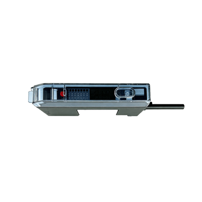
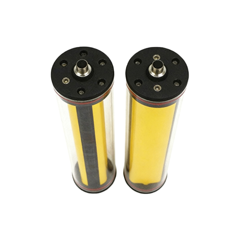
Before initiating the power-on sequence, it is crucial to have a comprehensive understanding of the photoelectric sensor system. A typical photoelectric sensor consists of three primary components: the emitter, which projects a light beam (often infrared, visible red, or laser); the receiver, which detects the presence or absence of the light beam; and the control circuitry housed within the sensor body. The sensor operates on the principle of light modulation and detection, where an interruption or reflection of the light beam triggers a change in the receiver's output state. This output is typically a solid-state transistor (PNP or NPN) or a relay contact. Familiarize yourself with the specific sensor model's datasheet, noting its operating voltage range (commonly 10-30V DC or 24-240V AC), output type, sensing mode (through-beam, retro-reflective, or diffuse), and connection diagram. Ensure you have the correct power supply unit (PSU) that matches the sensor's voltage and current requirements. A mismatch can lead to immediate failure or unreliable operation.
Pre-Power Safety and Connection Check
Safety is paramount in any industrial electrical procedure. Begin by ensuring that the main control panel or circuit supplying power to the sensor is locked out and tagged out (LOTO) to prevent accidental energization. Verify that the work area is dry and free from conductive debris. Proceed to inspect the sensor and its cabling. Check the sensor housing for any signs of physical damage, cracks, or contamination on the lens. Clean the lens with a soft, lint-free cloth if necessary. Examine the cable for cuts, abrasions, or damaged insulation. Next, confirm the wiring connections against the manufacturer's wiring diagram. For a standard 3-wire DC sensor, this typically involves connecting the brown wire (or red) to the positive DC supply voltage (+V), the blue wire to the common negative or 0V, and the black wire (or white) as the switched output load. The load (e.g., a PLC input, relay coil) is connected between the output wire and the positive supply. For 2-wire AC/DC sensors, ensure correct polarity if DC is used. Tighten all terminal screws to the specified torque to avoid loose connections that cause voltage drops or intermittent faults.
Applying Power and Initial Observation
With all connections verified and secure, you are ready to apply power. First, double-check that the power supply voltage is set correctly. If using a variable bench PSU, set it to the lower end of the sensor's operating range (e.g., 12V for a 10-30V DC sensor) initially. This conservative approach helps mitigate risk in case of an undetected wiring error. Momentarily apply power by switching on the PSU or closing the circuit breaker. Immediately observe the sensor's status indicators. Most modern photoelectric sensors are equipped with LED indicators: a stable or blinking green (or yellow) LED usually signifies power is present and the sensor is in its normal state (light received for a through-beam sensor in clear condition). A red LED often indicates a switching action or an alarm condition. Refer to the manual for the exact meaning of the LED patterns. If no LEDs illuminate, immediately disconnect power and re-check the wiring, fuse, and supply voltage. If the correct power LED is on, proceed to the next step.
Functional Testing and Alignment
Once stable power is confirmed, the sensor must be functionally tested and aligned. The method depends on the sensing mode. For a through-beam sensor, ensure the emitter and receiver are roughly aligned facing each other. The receiver's power/alignment LED should be solid, indicating it is receiving the emitter's beam. Carefully break the light beam with an opaque object. The output should switch states (e.g., from OFF to ON), and the output indicator LED (often orange or red) should activate. For a retro-reflective sensor, point it towards the reflector. The indicator should show a clear state. Break the beam to the reflector to trigger the output. For a diffuse (proximity) sensor, bring the target object within the specified sensing distance. Use the sensor's built-in potentiometer or teach-in function (if available) to adjust the sensitivity for reliable detection. Listen for an audible click if the sensor has a relay output, or use a multimeter in voltage mode to measure the output terminal's voltage change. Ensure the switching is crisp and repeatable without chatter.
Troubleshooting Common Power-On Issues
If the sensor fails to operate correctly after power application, systematic troubleshooting is required. Problem: No indicator LEDs illuminate. Solution: Verify power supply output with a multimeter. Check for blown fuses. Confirm wiring to the correct terminals and check for broken wires. Problem: Power LED is on, but no output switching occurs. Solution: Check if the load connected to the output is functional and within the sensor's rated current. Verify the sensing alignment; the beam might be misaligned or obstructed. For diffuse sensors, the target might be outside the sensing range or have low reflectivity. Adjust sensitivity. Problem: Sensor behaves erratically or switches unintentionally. Solution: Look for environmental interference such as ambient light (sunlight, strobes), vibration, or electrical noise from nearby motors or drives. Ensure the sensor is properly shielded and grounded. Use a shielded cable and connect the drain wire to ground. For AC sensors, ensure the load is not below the minimum required. Always consult the sensor's manual for specific error codes and diagnostic procedures.
Integration and Final System Verification
After successful standalone testing, integrate the sensor into the larger control system. Connect its output to the designated Programmable Logic Controller (PLC) input module, relay, or other control device. Re-apply power to the entire system. Observe the PLC's input status indicators or monitor the input tags in the Human-Machine Interface (HMI) software. Actuate the sensor by interrupting its beam or presenting a target. Confirm that the correct input bit toggles in the PLC logic. Run the machine or process through its full cycle in a controlled, safe manner to verify the sensor triggers actions (like stopping a conveyor, counting parts, or opening a valve) at the precise intended moments. Document the installation, including sensor model, serial number, location, and any sensitivity settings adjusted. This final verification ensures the photoelectric sensor is not only powered on but is also reliably performing its intended function within the automated system.