Understanding Proximity Sensor Terminal Configurations
Proximity switch sensors are fundamental components in industrial automation, detecting the presence or absence of an object without physical contact. The correct connection of their terminals is paramount for reliable operation. These sensors typically feature a standardized terminal block, often with three or four connection points. The most common configuration is the 3-wire type, comprising a positive supply voltage (brown wire), a negative or ground (blue wire), and a switched output signal (black wire). For DC sensors, the output can be either NPN (sinking) or PNP (sourcing), which dictates how the load is connected to the control system. A clear understanding of these terminal designations, as per IEC 60947-5-2 standards, is the first critical step before any wiring commences.
Step-by-Step Wiring Procedure for 3-Wire DC Sensors
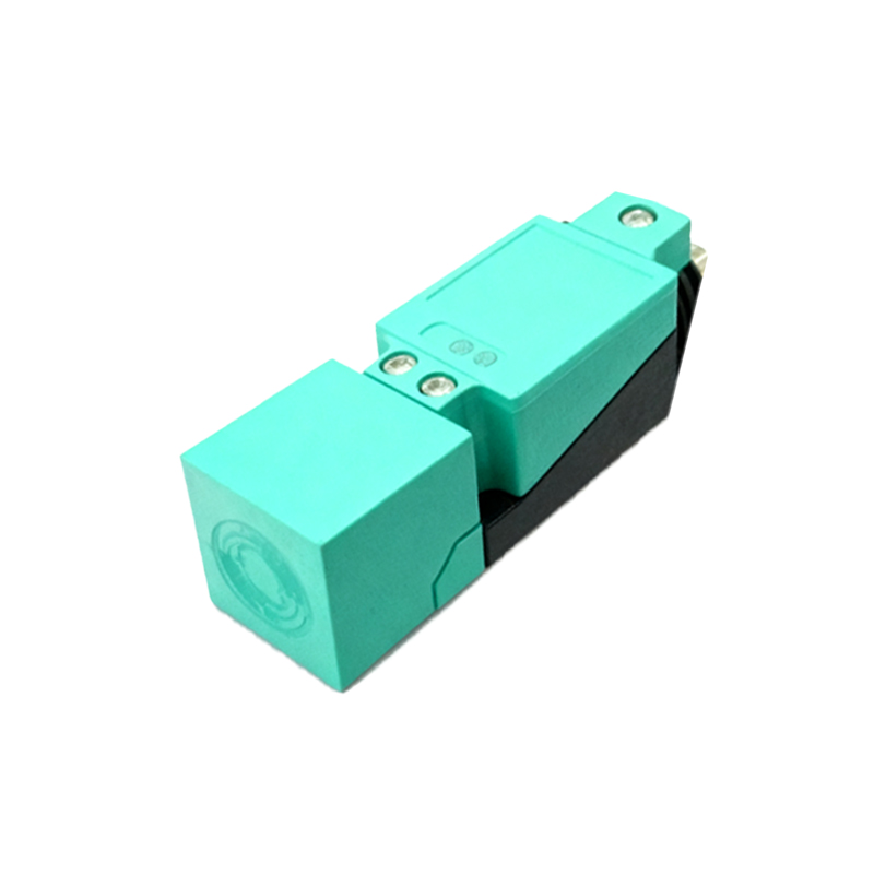
The wiring process must be executed with precision and adherence to safety protocols. First, ensure the power source is completely isolated and locked out. For a standard 3-wire DC PNP sensor, connect the brown wire to the positive DC supply terminal, typically +24V DC. Connect the blue wire to the common ground or 0V terminal of the power supply. The black wire, which is the switched output, is then connected to the input channel of your PLC, relay, or other control device. The load itself is connected between this black output wire and the positive supply. For an NPN sensor, the logic is inverted; the black output wire connects to the load, and the other side of the load is connected to the positive supply. Always refer to the sensor's datasheet for the exact wiring diagram, as colors and functions can vary by manufacturer.
Critical Considerations for Shielded Cables and Grounding
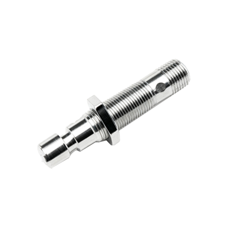
In electrically noisy industrial environments, proper shielding and grounding are non-negotiable for signal integrity. Many proximity sensors require the use of shielded cables. The cable shield, usually a braided copper mesh, must be grounded at only one end—typically at the control panel side—to prevent ground loops. This shield should be connected to a dedicated earth ground point, not daisy-chained with other grounds. Furthermore, the sensor housing itself often has a separate grounding terminal or requires a conductive mounting bracket for functional earth (FE) connection. This practice drains away electromagnetic interference (EMI) and enhances the sensor's immunity to noise from variable frequency drives (VFDs) or high-current switching equipment.
Diagnosing Common Terminal Connection Faults
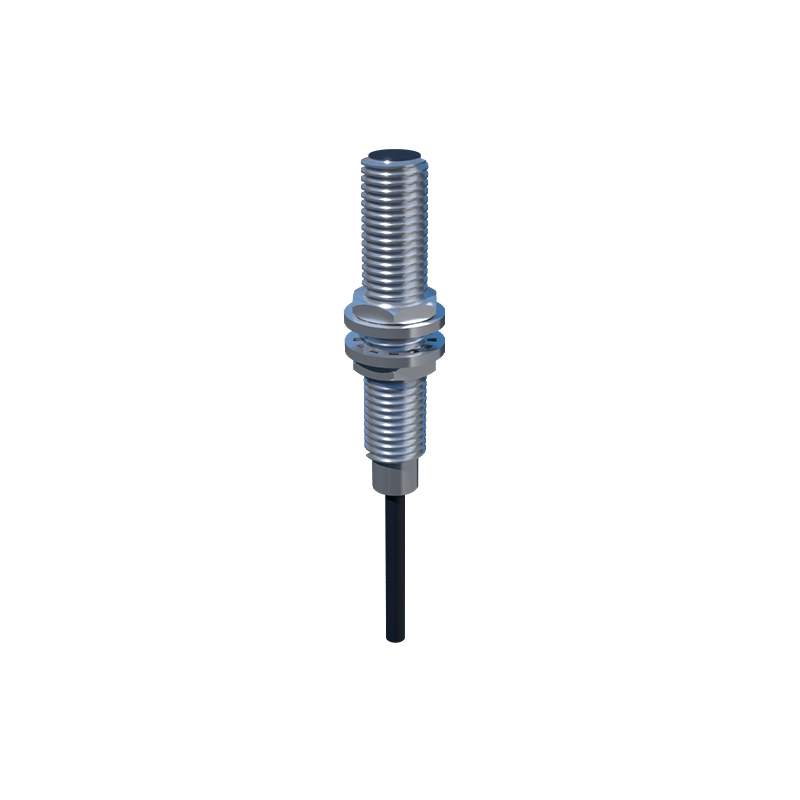
Even with careful installation, faults can occur. A systematic diagnostic approach saves valuable troubleshooting time. If a sensor fails to trigger, first verify the supply voltage at the sensor terminals with a multimeter. Incorrect polarity is a common mistake. Next, check the output state. A PNP sensor should switch the output to supply voltage (+24V) when activated. If voltage is present but the PLC does not register the input, the issue may lie in a faulty common connection or an incorrectly specified input card (sinking vs. sourcing). Intermittent operation often points to a loose terminal screw, damaged cable, or insufficient grounding, allowing electrical noise to disrupt the signal. Visual inspection of the terminal block for corrosion or overheating is also essential.
Best Practices for Terminal Maintenance and Longevity
Ensuring long-term reliability extends beyond the initial wiring. Use high-quality, stranded copper wire of the correct gauge, and always employ ferrules on stranded wires before inserting them into screw terminals to prevent fraying and ensure a gas-tight connection. Tighten terminal screws to the manufacturer's specified torque using a calibrated screwdriver; overtightening can damage the terminal, while undertightening leads to increased resistance and heat generation. During routine maintenance, inspect connections for signs of thermal stress, such as discoloration. Implementing a periodic check of terminal integrity, especially in environments with high vibration, prevents unexpected downtime and maintains optimal sensor performance throughout its service life.