Understanding the Core Function of Proximity Sensors
Proximity sensors are fundamental components in industrial automation, primarily designed to detect the presence or absence of an object within a specified range without physical contact. Their operation hinges on various physical principles, including electromagnetic fields, capacitance, and light. The most common types are inductive, capacitive, ultrasonic, and photoelectric sensors. The core output of a standard proximity sensor is a binary signal: ON or OFF, indicating detection or non-detection. This binary nature is key to understanding their primary function. They are engineered to respond to a change in the state of their sensing field caused by the intrusion of a target object. The sensor's electronics process this change and trigger a solid-state or relay output. Therefore, the fundamental design purpose is spatial detection, not temporal measurement. The sensor reacts to "if" and "where," not inherently to "how often" an event occurs over time.
Frequency Detection: An Indirect Capability, Not a Direct Measurement
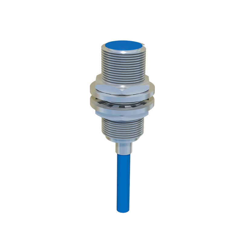
While a standard proximity sensor does not directly measure frequency like a dedicated tachometer or encoder, it can be instrumental in determining frequency indirectly. This application is common in rotational speed monitoring or event counting. For instance, an inductive proximity sensor positioned near a rotating gear or a shaft with a keyway will generate a pulsed output signal. Each passing tooth or feature causes the sensor to switch states. By feeding this pulsed output into a frequency counter, a programmable logic controller (PLC), or a timer module, the frequency of the pulses can be calculated. The derived frequency (pulses per second) can then be directly correlated to rotational speed (RPM) or linear speed. The critical factor here is that the sensor provides the raw pulse signal; the frequency analysis is performed by the subsequent control or measurement system.
Critical Factors Influencing Effective Frequency Monitoring
Several sensor specifications directly impact its suitability for indirect frequency detection applications. The most crucial is the sensor's response time or switching frequency, typically measured in Hertz (Hz). This specification defines the maximum number of on/off cycles the sensor can reliably perform per second. For example, a sensor with a 1 kHz switching frequency can theoretically handle up to 1000 detections per second. If the target object's passing frequency exceeds this limit, the sensor will miss counts, leading to inaccurate frequency readings. Other vital factors include the sensing distance, the size and material of the target, and the sensor's hysteresis. For high-frequency applications, engineers must select sensors with sufficiently high switching frequencies and minimal response time delays to ensure signal integrity and accuracy.
Sensor Type and Its Relevance to Frequency-Based Applications
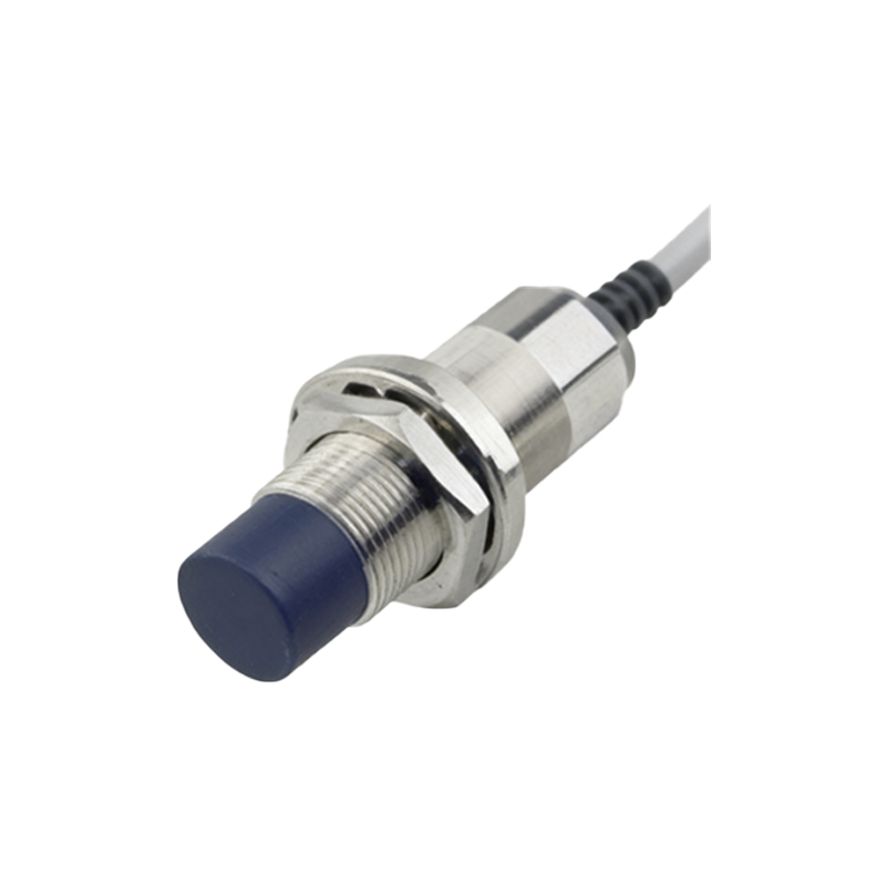
The type of proximity sensor chosen significantly affects the setup for frequency monitoring. Inductive sensors are ideal for detecting metallic objects and are widely used in RPM sensing of motors and gears. Capacitive sensors can detect non-metallic materials but may be susceptible to environmental changes. Photoelectric sensors, especially through-beam or retro-reflective types, offer very high switching frequencies and are excellent for counting small, fast-moving objects on a conveyor. Ultrasonic sensors, with slower response times, are less suited for high-frequency detection but can be used for slower event timing. Each type has a characteristic maximum switching frequency, which is the primary gatekeeper for its use in frequency-inferring tasks.
Practical Implementation and System Integration
In a practical implementation, the proximity sensor is merely the first component in the signal chain. The pulsed output must be connected to a device capable of time-based measurement. A common setup involves wiring a 3-wire DC sensor to a high-speed counter input on a PLC. The PLC program is then configured to measure the time between successive pulses (period) and calculate the inverse to determine frequency. Alternatively, dedicated frequency-to-voltage converters or standalone frequency meters can be used. Shielding and proper wiring are essential to prevent electrical noise from corrupting the pulse signal, which would cause erroneous frequency calculations. Calibration is also necessary to translate pulse frequency into a meaningful unit like RPM, using a known ratio (e.g., 60 pulses per revolution).
Limitations and Alternative Solutions for Direct Frequency Sensing
It is paramount to recognize the limitations. Standard proximity sensors are not precision frequency measurement devices. Their accuracy in frequency derivation depends on the consistency of the target, stability of the sensing gap, and the precision of the subsequent measuring electronics. For applications requiring direct, high-accuracy frequency measurement of a signal (like an AC power line or a vibration frequency), specialized sensors like vibration transducers, tachometers, optical encoders, or dedicated frequency sensors are the appropriate choice. These devices are designed to output a signal directly proportional to frequency, offering higher resolution, accuracy, and reliability for critical monitoring