Introduction to Photoelectric Sensors
Photoelectric sensors are widely used in industrial automation for detecting the presence, absence, or distance of objects. They operate by emitting a light beam, typically from an LED or laser diode, and measuring the reflected or interrupted light using a phototransistor or photodiode. These sensors offer non-contact detection, high precision, and reliability, making them ideal for applications like object counting, position sensing, and safety systems. In this article, we will explore how to design and simulate a basic photoelectric sensor circuit using Proteus simulation software, providing a practical guide for engineers and hobbyists.
Key Components of the Circuit
The core components of a photoelectric sensor simulation in Proteus include a light-emitting element, a light-detecting element, and supporting circuitry. For the emitter, an infrared LED is commonly used due to its efficiency and minimal interference with ambient light. The detector can be a phototransistor, which amplifies the light signal, or a photodiode for faster response times. Additional components such as resistors, capacitors, and operational amplifiers are integrated to condition the signal. In Proteus, these components are available in the library, allowing users to drag and drop them into the schematic editor. Proper selection of component values, like resistor ratings for current limiting, is crucial to ensure the circuit operates within safe parameters and achieves desired sensitivity.
Building the Schematic in Proteus
To start the simulation, open Proteus and create a new project. Search for components like "IR LED" and "Phototransistor" in the library and place them on the workspace. Connect the IR LED in series with a current-limiting resistor to a power supply, typically 5V, to control the light intensity. For the phototransistor, connect it in a voltage divider configuration with a pull-up resistor to generate an output voltage that changes with light exposure. Add an op-amp, such as the LM358, to amplify the weak signal from the phototransistor if needed. Use wiring tools to link all parts, ensuring proper grounding and power connections. This schematic forms the basis for testing the sensor's response to simulated objects or light variations.
Simulation and Testing Procedures
Once the schematic is complete, proceed to simulation by clicking the "Play" button in Proteus. The software allows you to simulate real-time behavior, where you can introduce virtual objects to interrupt the light path between the IR LED and phototransistor. Observe the output voltage on a virtual oscilloscope or multimeter; it should drop when an object blocks the light, indicating detection. Adjust component values, such as increasing the resistor for higher sensitivity, and rerun the simulation to optimize performance. Proteus also supports adding graphs to plot voltage over time, helping analyze response speed and stability. This iterative testing process ensures the circuit meets design specifications before physical implementation.
Common Applications and Variations
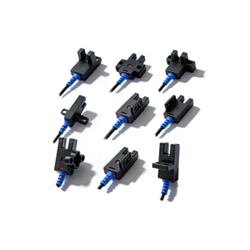
Photoelectric sensor circuits simulated in Proteus can be adapted for various industrial and DIY projects. For example, they are used in conveyor belt systems to count products, in security alarms to detect intrusions, or in robotics for obstacle avoidance. Variations include reflective sensors, where the emitter and detector are placed side-by-side to sense light bounced off a surface, and through-beam sensors, with separate units for emission and reception. In Proteus, you can modify the circuit to include microcontrollers like Arduino for advanced logic, simulating how the sensor interfaces with digital systems. These applications demonstrate the versatility of photoelectric sensors and the value of simulation in reducing development time and costs.
Best Practices for Optimization
To enhance the simulation accuracy and circuit efficiency, follow best practices in Proteus. Use decoupling capacitors near power sources to minimize noise, and select components with realistic models from the library to mirror real-world behavior. Calibrate the sensor by simulating different environmental conditions, such as ambient light changes, to ensure robustness. Additionally, document the design with notes in Proteus for future reference, and consider simulating failure modes, like component faults, to improve reliability. By leveraging Proteus's tools, engineers can refine their photoelectric sensor designs, achieving optimal performance for specific use cases before moving to prototyping.
Conclusion and Further Resources
In summary, designing a photoelectric sensor circuit in Proteus provides a cost-effective way to validate concepts and troubleshoot issues. This guide covers the essential steps from component selection to simulation testing, aimed at supporting engineers in creating reliable detection systems. For further learning, explore Proteus tutorials online or experiment with advanced features like PCB layout integration. By mastering these simulations, you can accelerate innovation in automation and electronics, contributing to smarter industrial solutions.