Introduction to Proximity Sensor Fundamentals
Proximity switch sensors, often simply called proximity sensors, are non-contact electronic devices designed to detect the presence or absence of an object within a specified sensing range. Unlike mechanical limit switches, they operate without physical contact, making them ideal for harsh environments, high-speed applications, and scenarios requiring high reliability and long operational life. The core principle involves generating an electromagnetic field or beam and detecting changes in that field caused by a target object. The internal architecture is meticulously engineered to convert this detection into a clean, usable electrical signal for control systems. This article delves into the intricate internal components and their functional interplay within a standard inductive proximity sensor, the most common industrial type used for detecting metallic objects.
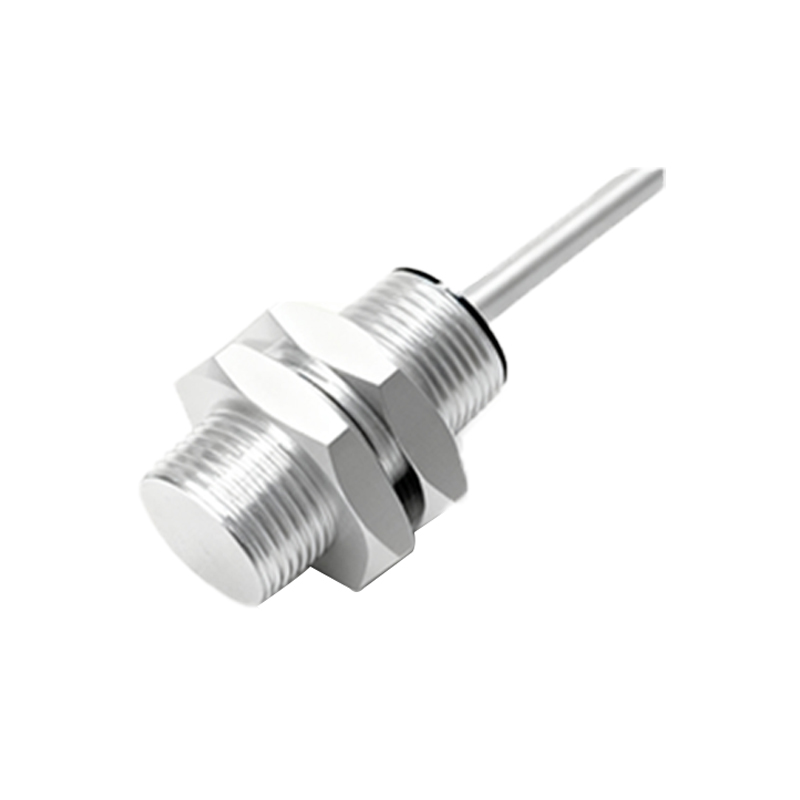
The Sensing Coil and Ferrite Core Assembly
At the very heart of an inductive proximity sensor lies the oscillator circuit, and its central component is the sensing coil wound around a ferrite core. This coil is typically made of fine copper wire and is responsible for generating a high-frequency alternating electromagnetic field at the sensor's active face. The ferrite core, with its high magnetic permeability, concentrates and directs this field forward, enhancing sensitivity and defining the sensor's nominal sensing range. The oscillator, often a Colpitts or Hartley type, is designed to sustain oscillations at a stable frequency, typically between 100 kHz and 1 MHz. The precise construction of this coil-core assembly is critical; it determines the sensor's performance characteristics, including its switching frequency, hysteresis, and immunity to electromagnetic interference.
The Demodulation and Signal Processing Circuitry
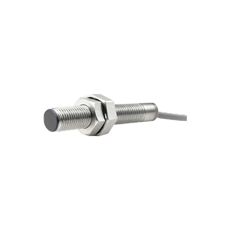
When a metallic target enters the electromagnetic field, eddy currents are induced on the target's surface. These currents absorb energy from the oscillator, causing a measurable decrease in the oscillation amplitude. This subtle change is the primary signal indicating target presence. The internal circuitry must reliably detect this change. The demodulator stage rectifies and filters the high-frequency AC signal from the oscillator, converting the amplitude drop into a smooth DC voltage shift. This analog signal then passes to a threshold detector or Schmitt trigger circuit. This stage is crucial for providing a sharp, clean switching action, eliminating chatter, and establishing the sensor's hysteresis—the difference between the switch-on and switch-off points, which prevents rapid toggling when a target is at the sensing edge.
Output Switching Stage and Protection Components
The processed signal from the threshold detector drives the output stage, which interfaces with the external programmable logic controller (PLC) or relay. For a solid-state DC sensor, this typically involves a transistor (NPN or PNP) operating in saturation or cutoff mode to act as a switch. For AC sensors, a triac is commonly used. This stage is robustly protected. Series resistors limit current, while transient voltage suppression (TVS) diodes or metal-oxide varistors (MOVs) protect against voltage spikes and surges on the supply lines. Reverse polarity protection diodes are integrated to prevent damage if the power wires are accidentally connected incorrectly. In more advanced models, short-circuit and overload protection is also built into the output stage, automatically limiting current if the output is accidentally shorted to ground or supply.
Housing, Encapsulation, and Environmental Sealing
The internal electronic components are housed within a robust body, usually made of brass, stainless steel, or high-grade plastic like PBT or PPS. The sensing face is a critical area, often made of a specialized plastic compound that allows the electromagnetic field to pass through while protecting the coil. To ensure longevity in industrial settings, the entire internal cavity is potted with a resilient epoxy resin compound. This potting material serves multiple vital functions: it securely anchors all components against vibration and shock, provides exceptional heat dissipation from the power transistor, and most importantly, creates a hermetic seal against moisture, dust, oils, coolants, and other contaminants. This encapsulation process is what grants many proximity sensors an Ingress Protection (IP) rating of IP67 or higher, allowing them to function reliably in washdown or submerged conditions.
Specialized Variants and Internal Adaptations
While the inductive principle is standard, internal structures adapt for specialized types. Capacitive proximity sensors, used for non-metallic materials, feature different electrode plate designs around the sensing face to create a capacitive field. Ultrasonic sensors incorporate a piezoelectric transducer for emitting and receiving sound waves, along with sophisticated timing circuitry. Magnetic (reed or Hall-effect) proximity sensors contain a magnetically sensitive element internally. Furthermore, analog output sensors replace the simple switching transistor with a circuit that provides a continuous current or voltage output proportional to the target distance. All these variants share the same core design philosophy: robust construction, integrated signal processing, and comprehensive protection within a sealed housing to