Understanding Analog Proximity Sensor Fundamentals
Analog proximity sensors are critical components in modern industrial automation, providing continuous distance or position feedback. Unlike their digital counterparts that offer a simple on/off signal, analog sensors output a variable signal—typically voltage (0-10V) or current (4-20mA)—that is directly proportional to the distance of the target object. This continuous data stream enables precise monitoring and control in applications such as position sensing, thickness measurement, and edge guiding. The core sensing technologies include inductive, capacitive, and ultrasonic principles, each suited for different target materials and environmental conditions. Selecting the correct sensor type is the foundational step before addressing the wiring configuration.
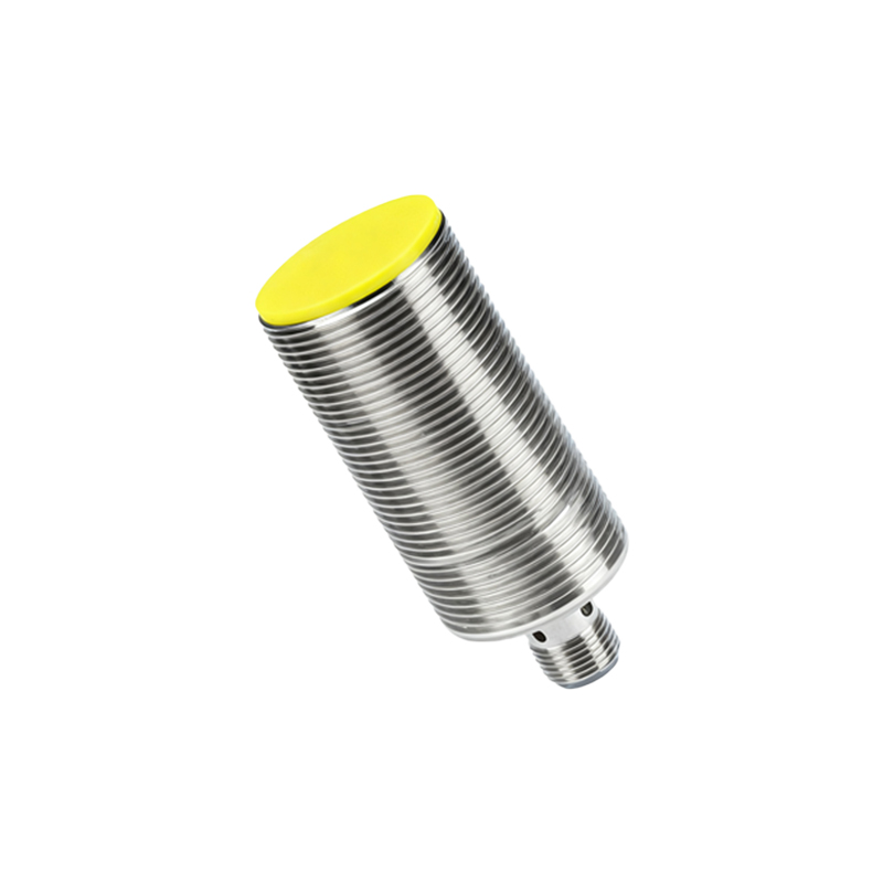
Core Components and Terminal Identification
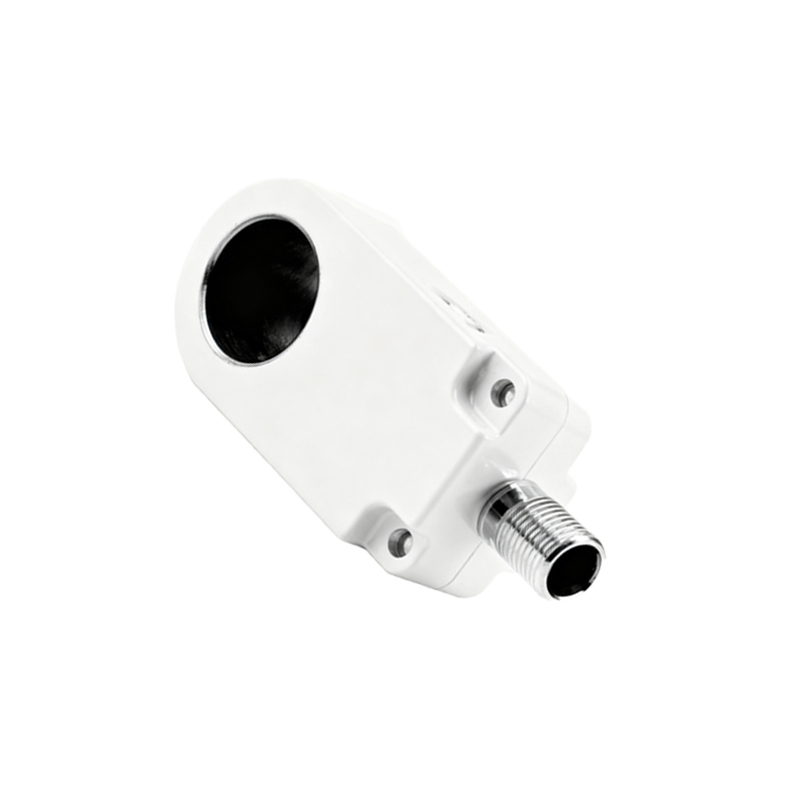
A standard three-wire analog proximity sensor features three distinct terminals: Brown (or +V), Blue (or 0V/GND), and Black (Signal Output). The brown wire connects to the positive supply voltage, which commonly ranges from 10-30V DC depending on the sensor model. The blue wire is connected to the power supply's negative terminal or ground (0V). The critical black wire carries the analog output signal. For current output sensors (4-20mA), this wire supplies the loop current. For voltage output sensors (0-10V), this wire provides the variable voltage. Some advanced models may include a fourth wire (often white) for diagnostic or configuration functions. Always consult the manufacturer's datasheet for the specific pinout and specifications, as color coding can occasionally vary.
Standard 3-Wire Wiring Configuration
The most prevalent wiring scheme involves connecting a three-wire sensor to a DC power supply and a programmable logic controller (PLC) or analog input module. First, connect the brown wire to the positive terminal of the DC power supply (e.g., +24V). Second, connect the blue wire to the negative terminal of the same DC power supply (0V). This completes the power circuit. Third, connect the black (signal) wire to the positive terminal of the PLC's analog input channel. Finally, connect the negative terminal of that same PLC analog input channel back to the power supply's 0V (blue wire terminal). This creates a complete circuit for the analog signal. Ensure the power supply voltage matches the sensor's requirement and that the PLC input is correctly configured for either voltage or current measurement.
Connecting to PLC Analog Input Modules
Proper integration with a PLC is crucial for system functionality. For a 4-20mA current loop sensor, the PLC analog input module must be set to current mode. Often, this involves moving a jumper or configuring a DIP switch on the module itself. The black wire from the sensor connects to the positive current input terminal (e.g., I+), while the corresponding negative terminal (I-) is wired to the power supply's 0V. For 0-10V voltage sensors, the black wire connects to the voltage input terminal (V+), and the common terminal (COM) is linked to 0V. Inside the PLC programming software, scale the raw analog input value (e.g., 0-27648 for a typical 16-bit module) to meaningful engineering units like millimeters or inches based on the sensor's sensing range.
Shielding and Noise Reduction Practices
Industrial environments are rich with electromagnetic interference (EMI) from motors, drives, and switching equipment, which can distort sensitive analog signals. To mitigate noise, always use shielded cable for the sensor connections. Connect the cable's shield braid to a functional earth ground at the PLC cabinet or control panel, typically at a single point to avoid ground loops. Do not connect the shield at both ends. Keep sensor cables away from high-voltage power lines and AC conductors. If possible, route them separately in dedicated cable trays. For long cable runs exceeding 50 meters, consider using analog signal conditioners or isolators to boost signal integrity and protect the PLC inputs from transient voltages.
Diagnosing Common Wiring and Signal Issues
Troubleshooting begins with systematic checks. A sensor with no output can often be traced to incorrect power supply polarity or voltage. Verify voltage at the brown and blue terminals with a multimeter. If power is correct but the PLC reads zero, check the signal wire connection and the PLC's input configuration. A signal stuck at maximum (e.g., 20mA or 10V) may indicate a sensor fault or a wiring short circuit. Erratic or noisy readings point to poor shielding, grounding issues, or an insufficient power supply. Always measure the analog signal directly at the sensor's black wire with a multimeter set to voltage or current to determine if the issue originates at the sensor or in the downstream wiring/