Understanding the Fundamentals of Photoelectric Sensing
Photoelectric sensors are pivotal components in modern industrial automation, primarily used for detecting the presence, absence, or position of objects. Their operation hinges on emitting a beam of light (visible, infrared, or laser) and detecting changes in the received light intensity caused by an interrupting object. When applied to speed or rotational measurement, they function as non-contact tachometers. A reflective or through-beam sensor is typically paired with a marked or slotted disc attached to a rotating shaft. Each pass of a mark or slot generates a pulse, and the frequency of these pulses directly correlates to the rotational speed. The core question of "what speed is suitable" is not answered by a single universal value but by a complex interplay of the sensor's specifications, the application's physical parameters, and the required measurement accuracy.
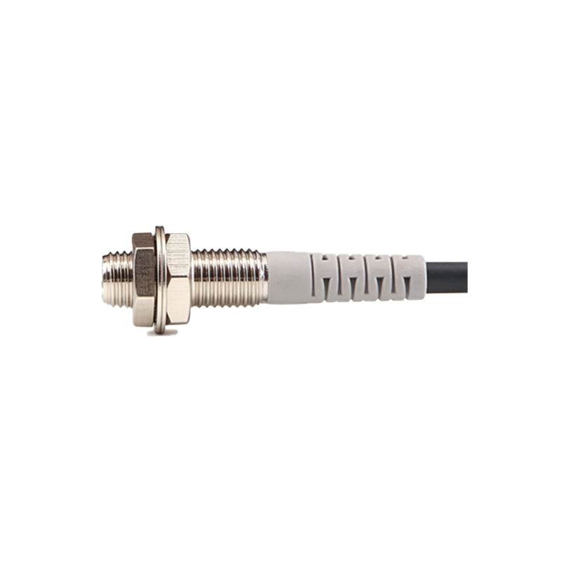
Key Technical Specifications Governing Maximum Speed
The absolute upper limit for a photoelectric sensor in speed detection is dictated by its response time, often measured in milliseconds (ms) or microseconds (µs). This specification defines how quickly the sensor's output can switch after detecting a change in light condition. For instance, a sensor with a 1 ms response time can theoretically handle up to 1000 on/off cycles per second. In a setup where a disc has 10 slots, the maximum measurable speed would be (1000 cycles/second) / (10 slots/revolution) = 100 revolutions per second, or 6000 RPM. High-speed applications demand sensors with response times in the microsecond range. Furthermore, the light source modulation frequency is critical. Many modern sensors use a modulated LED pulse to avoid interference from ambient light. The modulation frequency must be significantly higher than the expected pulse frequency from the target to ensure reliable detection.
Application-Specific Factors Influencing Optimal Speed Range
Beyond raw specifications, the "suitable" speed is heavily influenced by the physical setup. The size and number of marks on the target disc are paramount. More marks provide higher resolution but generate a higher frequency signal for a given speed. The sensor must be capable of resolving each individual mark. The contrast between the mark and the background, the reflectivity of the surface, and the alignment of the sensor all affect the signal integrity. At very high speeds, mechanical factors like disc wobble or vibration can cause erratic readings. Therefore, the optimal operational speed is often well below the theoretical maximum, providing a safety margin for signal stability and system reliability. For conveyor belt monitoring, speeds may range from a few RPM to several hundred RPM, while in motor or turbine shaft monitoring, speeds can extend into tens of thousands of RPM.
The Critical Role of the Evaluation Electronics and Output
The photoelectric sensor is only one part of the measurement chain. The evaluation unit or controller (like a PLC) that processes the sensor's pulse signal must have a fast enough input sampling rate or a dedicated high-speed counter input to accurately capture the frequency. The sensor's output type also matters. A standard digital PNP/NPN output may have switching frequency limits, whereas analog output sensors (0-10V, 4-20mA) proportional to speed are used for continuous monitoring but may have lower bandwidth. For precise RPM measurement, especially at variable speeds, a system that measures the time period between pulses can offer higher accuracy at lower speeds compared to a pure frequency-counting method.
Practical Guidelines for Selection and Setup
To determine a suitable speed for your application, start by defining the maximum expected rotational speed (RPMmax) and the number of pulses per revolution (N). Calculate the maximum output frequency: Fmax = (RPMmax * N) / 60. Select a photoelectric sensor whose response time allows for a switching frequency at least 1.5 to 2 times higher than your calculated Fmax. Choose a sensor with a beam spot size smaller than the width of your target marks. Ensure the sensing distance and mounting are robust against environmental factors like dust, oil, or temperature fluctuations, which can degrade performance at any speed. For critical high-speed applications, laser-based sensors often provide the superior focus, response time, and signal-to-noise ratio required.
Conclusion: Balancing Performance and Reliability
There is no single "correct" speed for a photoelectric sensor in rotational measurement. The optimal speed is a system-level compromise that balances the sensor's inherent capabilities (response time, beam quality), the mechanical and optical characteristics of the target, and the processing capabilities of the downstream electronics. A prudent engineering approach involves selecting a sensor with a headroom of at least 50-100% beyond the calculated maximum frequency requirement. This ensures consistent, accurate, and reliable operation throughout the lifecycle of the machinery, preventing measurement errors, missed counts, or system downtime that can occur when operating too close to the sensor's physical limits. Always consult the sensor's detailed datasheet and consider real-world environmental conditions during the design phase.